OT: discrete opamp
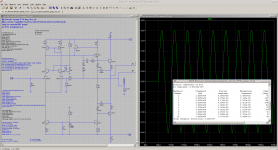
I am currently designing my own discrete opamp using BF245A.
Currently measured results at unity gain:
0.002% THD20k@2.7V RMS @ 600R (bw 80 kHz)
slewrate 20V/µs
( compared using my VP7723D: LM4562 gives me 0.001% THD20k@2.7V RMS @ 600R, bw 80 kHz)
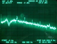
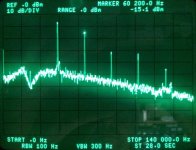
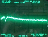
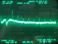
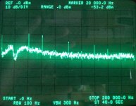
To get a fealing of measurement quality I have attached spectrum analyser HP3583 screenshots from 20khz residual (2nd picture) and the analyser residual itself for comparison (1st picture).
Is it worth continue with this discrete opamp design?
BR, Toni
I am currently designing my own discrete opamp using BF245A.
Currently measured results at unity gain:
0.002% THD20k@2.7V RMS @ 600R (bw 80 kHz)
slewrate 20V/µs
( compared using my VP7723D: LM4562 gives me 0.001% THD20k@2.7V RMS @ 600R, bw 80 kHz)
To get a fealing of measurement quality I have attached spectrum analyser HP3583 screenshots from 20khz residual (2nd picture) and the analyser residual itself for comparison (1st picture).
Is it worth continue with this discrete opamp design?
BR, Toni
Attachments
Last edited:
Try to get PSRR higher, especially in the treble, as most opamps have a PSRR corner under 20KHz. In addition, try to make it completely fault tolerant with minimal glitching, and no oscillation bursts during faults. Fault instability can be highly dependent on fault PSRR in concert with the decoupling scheme. For an opamp where speed is high, tolerance to adverse decoupling is a great boon.
Hi Tony and others,
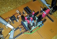
Looking at your pcb, seeing all those components standing up, it is just crying to be done in SMT. If certain parts only come in THT, have to stay with them, but many can be changed. How's your eye sight?
Now the big question, can you hear any difference between VP7723D & LM4562.
Can you post the .asc file please
Thanks
Rick
Looking at your pcb, seeing all those components standing up, it is just crying to be done in SMT. If certain parts only come in THT, have to stay with them, but many can be changed. How's your eye sight?
Makes you wonder, doesn't it.Is it worth continue with this discrete opamp design?
Now the big question, can you hear any difference between VP7723D & LM4562.
Can you post the .asc file please
Thanks
Rick
Try to get PSRR higher, especially in the treble, as most opamps have a PSRR corner under 20KHz. In addition, try to make it completely fault tolerant with minimal glitching, and no oscillation bursts during faults. Fault instability can be highly dependent on fault PSRR in concert with the decoupling scheme. For an opamp where speed is high, tolerance to adverse decoupling is a great boon.
Dear keantoken,
thanks for superfast reply. PSRR from negative supply is 130db at 1kHz and 106 dB at 20kHz. Think good enough.
PSRR from positive supply is about 106db at 1kHz and 61db at 20kHz. Should we do here something?
Hi Tony and others,
Looking at your pcb, seeing all those components standing up, it is just crying to be done in SMT. If certain parts only come in THT, have to stay with them, but many can be changed. How's your eye sight?
Makes you wonder, doesn't it.
Now the big question, can you hear any difference between VP7723D & LM4562.
Can you post the .asc file please
Thanks
Rick
Dear Rick,
of course we could use SMT parts - but my eyes are some decades old and my fingers are moving sometimes so fast that I can't see the flight route of an SMT device.
 I hate those small SMT devices.
So I decided to develop this opamp with standard discrete through hole parts.
VP7723D is my audio analyzer ... hard to compare with the sound of an LM4562.
at what end of what?
Hi, I missed this. I'm asking about speakers, but 17uV is pretty low. EMI and RFI will be well above this.
I'm guessing that the noisy BJT amps are the ones that use large LTP degeneration. There are some advantages to larger degeneration when it comes to fault recovery, so it would be useful to know how much noise is acceptable. I couldn't find the answer even in Cordell's book.
OT: discrete opamp
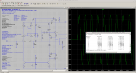
attached the schematic with real life compensation values. The simulated 0.002% THD20k@4Vp@600R is exactly the measured one!
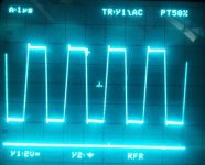
Also the simulated and measured square wave figures are nearly exactly!
So our pole gurus are able to help here?
Use "mylibs.lib" from above asc files.
BR, Toni
attached the schematic with real life compensation values. The simulated 0.002% THD20k@4Vp@600R is exactly the measured one!
Also the simulated and measured square wave figures are nearly exactly!
So our pole gurus are able to help here?
Use "mylibs.lib" from above asc files.
BR, Toni
Attachments
Duh, okay I meant, comparing the sound of the discrete Op-amp vs the TI LM4562?
I remember the article in Audio Express (Metz Pre-amp) Mr. Metz had to rationalize a discrete implementation vs op-amp, he finally decided to use TI OPA2134's.
DB tests have clearly to be done afterwards. Currently I measure using audio analyzer and spectrum analyzer always in comparison to the industry standard devices NE5532, LM4562 and LME49990.
Afterwards I need to build a blackbox where the others don't know which switch position is the LM4562 or the my_doa_v2 ...
OT: discrete opamp
Now with a capacitance multiplier to better PSRR on positive supply: about 91dB at 1kHz and 90dB 20kHz (can be further bettered on increasing C1).
Optimized compensation - 0.001% THD20k@4Vpk@600R
Very small transient overshoot < 5%
Now with a capacitance multiplier to better PSRR on positive supply: about 91dB at 1kHz and 90dB 20kHz (can be further bettered on increasing C1).
Optimized compensation - 0.001% THD20k@4Vpk@600R
Very small transient overshoot < 5%
Attachments
OT: discrete opamp
20kHz / unity gain / 4Vpk
From left to right:
20kHz / unity gain / 4Vpk
From left to right:
- Analyser reference residual no bw limit
- My_DOA residual no bw limit
- LM4562 residual no bw limit
Attachments
If you can simplify your Miller/Cherry compensation, its possible to get excellent PSR on your +ve rail by connecting a similar circuit to inject current into the mirror.Now with a capacitance multiplier to better PSRR on positive supply: about 91dB at 1kHz and 90dB 20kHz (can be further bettered on increasing C1).
I've done this successfully in 'real life' and describe it in #2060 of discrete-opamp-open-design
It's C5 in the circuit I posted there.
43pF from the other side of the current mirror to ground will increase PSRR. However it depends on matching of the capacitances, so if your tolerance is 5% you will get at least 26db increase in PSRR. TPC can raise PSRR higher than that (with the resistor to VAS rail), although it may be worse at higher frequencies if the pole is low enough.
Connecting miller compensation to Q1's emitter instead will give higher PSRR than either of these options and won't be reliant on component tolerance.
kgrlee, to make a link go to the right post for everyone regardless of forum settings, edit out the page number in the URL, like this:
http://www.diyaudio.com/forums/analog-line-level/218373-discrete-opamp-open-design.html#post3238467
Dear kgrlee, keantoken,
thanks for helping.
A) Using capacitance multiplier C1=100n and adding a 47p at collector of Q5 to ground gives excellent results:
PSRR 1kHz 108db
PSRR 20kHz 117db
B) Using only a 43p at collector of Q5 to ground gives good results:
PSRR 1kHz 97db
PSRR 20kHz 83db
C) Using only a 43p at current mirror bases of Q2/Q5 to ground gives also good results:
PSRR 1kHz 97db
PSRR 20kHz 83db
D) Using only capacitance multiplier with C1=1µF gives excellent results:
PSRR 1kHz 111db
PSRR 20kHz 111db
If I have enough room on the small pcb I will use variant D otherwise B or C
BR, Toni
Yes to TPC with resistor to VAS rail.43pF from the other side of the current mirror to ground will increase PSRR. However it depends on matching of the capacitances, so if your tolerance is 5% you will get at least 26db increase in PSRR. TPC can raise PSRR higher than that (with the resistor to VAS rail), although it may be worse at higher frequencies if the pole is low enough.
But this technique needs very simple Miller/Cherry compensation. Toni's R5+C5 Miller & R6+C7 Cherry requires a similarly complex network between earth and Q5 collector.
I found in 'real life' that using NPO ceramics from the same batch were enough to guarantee good PSR if you took care with layout and used a very simple circuit like my JFET 990 circuit in #2060 of discrete-opamp-open-design
At the moment, Toni's compensation is too complex to use this simple technique. Tony, a single 43p cap will be a compromise.
For the right circuit in 'real life', the PSR nulls over a very wide frequency range .. better than TPC versions.
Layout then becomes critical which highlights the importance of stray capacitances to PSR.
Guru Wurcer uses a similar technique in his AD797 datasheet which is the dual of my method. His capacitor to earth is the main compensation while my main compensation is the Cherry cap.
Yes. This is one of the better solutions for PSR but I find problems with stability doing this. THD isn't quite as good as 'pure Cherry'.Connecting miller compensation to Q1's emitter instead will give higher PSRR than either of these options and won't be reliant on component tolerance.
If you have good results for this, can you post a *.ASC?
Last edited:
... it is unstable in simulation ......
Connecting miller compensation to Q1's emitter instead will give higher PSRR than either of these options and won't be reliant on component tolerance.
...
Hmm. I've never actually used that idea much, so maybe this is why. I thought maybe a cap (or RC) across the C-E of Q1, which may worsen PSRR, and making sure not to make Q1 an oscillator this way. Other than that, you may need to pay attention to RF decoupling of J1's base because it becomes a positive feedback node when miller feedback is brought to its drain.
- Home
- Amplifiers
- Solid State
- 2stageEF high performance class AB power amp / 200W8R / 400W4R