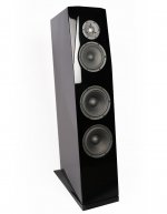
Just now I noticed a similar speaker build as mine with same drivers, active crossover, elliptical waveguide etc here:
Hifi Vintage DIY fair with pictures | Audio Science Review (ASR) Forum
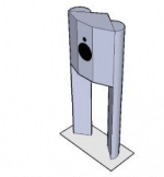
What interested me the most was that vertical spacing between mid and tweeter.. (looks almost the same spacing as I had on the prototype baffle)
Hifi Vintage DIY fair with pictures | Audio Science Review (ASR) Forum
What interested me the most was that vertical spacing between mid and tweeter..
(looks almost the same spacing as I had on the prototype baffle)Just now I noticed a similar speaker build as mine with same drivers, active crossover, elliptical waveguide etc here:
Hifi Vintage DIY fair with pictures | Audio Science Review (ASR) Forum
What interested me the most was that vertical spacing between mid and tweeter..
So there is a school of thought where the effect of floor and ceiling reflections are considered seriously while designing the vertical spacing as tmuikku had pointed out initially in this thread. I can sort of see this in the construction of the above speakers here:
faktiskt.io • Visa trad - Jag och mitt ljud ; Nu har jag lurat fardigt
I found even a video recording of above speaker (just for seeing it live in action. I wouldn't judge sound based on a youtube video..
):En ny hogtalare 2 - YouTube
There are some documents which are referenced which I think are in Swedish and I am unable to read and understand it. Hopefully, will try to use google translate to some extent. In the spirit of learning what others have done before me with a similar set of drivers, I will try to read the above thread and get some learnings from it too.
I'm not sure about the first but I agree with the second
Fluid could you expand a bit? I reread Olson paper, made a bit of simulation with the tools i have access to and i think i can see your point but i still think if Earl Geddes or the designer of Grimm audio LS choosen to bother implementing large roundover despite the difficulty in realisation there is a reason.
But maybe it is just design objective dependent? Maybe a truncated parallelopiped/pyramid is better within other design objective?
In 3D BEM sims I don't see any appreciable difference between a roundover or a 45 degree chamfer of the same depth. The roundover is much harder to model (and can come out looking worse if not enough mesh resolution is used) but otherwise they seem interchangeable to me on a cabinet edge.Fluid could you expand a bit? I reread Olson paper, made a bit of simulation with the tools i have access to and i think i can see your point but i still think if Earl Geddes or the designer of Grimm audio LS choosen to bother implementing large roundover despite the difficulty in realisation there is a reason.
But maybe it is just design objective dependent? Maybe a truncated parallelopiped/pyramid is better within other design objective?
A facet is different again as it is not always the same effective depth all the way down. It is a good way of dealing with tweeters and mids in a 2 or 3 way design as it concentrates the diffraction reduction where it is most needed and allows a minimal baffle area around each driver. Lots of designs aim for this last part.
Earl's speaker cabinets are made differently using Renshape board and so a large roundover is easy enough to make in that sort of material and it aids in making a smoother termination to the waveguide.
Grimm used an aluminium channel for practicality. It is much easier to make and round the vertical edge than this alternative.
I don't see any clash with this and Olsen's depictions. Beside a full sphere (a) the parallelpiped (j) or long chamfer (l) have the smoothest responses.
Attachments
Last edited:
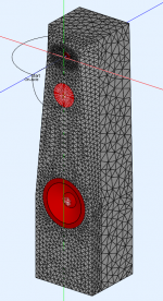
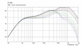
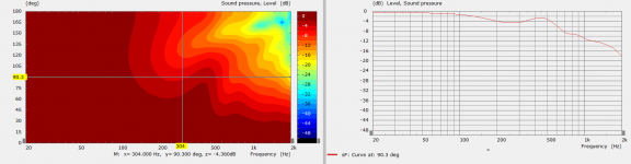
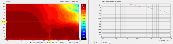
Simulation on the Rockport style enclosure started with results for the woofer. This does not look really any different than before but this time there are separate Horizontal and Vertical responses and a Lumped element has been used on the woofer to represent the Thiele Small Parameters and a 35 L sealed enclosure. Distance 2.5m.
Mid and tweeter to be done separately but the sim time will be quite long to get any real frequency resolution so that will come later.
If the woofer was crossed out between 300 and 400Hz then all there would be is a gentle downslope to the off axis rather than the obvious bump. Whether this is practical with the other driver and it's predicted response is unclear.
The mid is 164mm CTC from the tweeter, this is 1.2 wavelengths at 2500 and 1 wavelength at 2000. Even if placed virtually on top of each other they would struggle to be much less than a wavelength unless the tweeter is run much lower.
Attachments
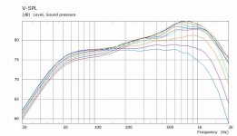
Simulation on the Rockport style enclosure started with results for the woofer. This does not look really any different than before but this time there are separate Horizontal and Vertical responses and a Lumped element has been used on the woofer to represent the Thiele Small Parameters and a 35 L sealed enclosure. Distance 2.5m.
Mid and tweeter to be done separately but the sim time will be quite long to get any real frequency resolution so that will come later.
If the woofer was crossed out between 300 and 400Hz then all there would be is a gentle downslope to the off axis rather than the obvious bump. Whether this is practical with the other driver and it's predicted response is unclear.
The mid is 164mm CTC from the tweeter, this is 1.2 wavelengths at 2500 and 1 wavelength at 2000. Even if placed virtually on top of each other they would struggle to be much less than a wavelength unless the tweeter is run much lower.
Thanks fluid..
Initially, my plan was to cross the woofer to the mid somewhere between 300 and 400 (close to 400 Hz). Back then I didn't know about the cabinet diffraction-related effects that we have seen till now in the previous sims. Could you let me know why it might not be possible to cross the mid to woofer around the 350 Hz range. Is it because of the peaky diffraction effects we had seen in earlier sims or because this 5 inch driver is not suitable to crossing that low?
Initially, my prototype baffle c-c between mid and tweeter was 165mm and the mid to tweeter crossover plan was also somewhere between 2k to 2.5 kHz due to the non smooth behavior of this mid driver's response beyond 2.5kHz compared to something like a Wavecor WF120 series driver..
But I will wait for your sims to complete so that we will have a better idea above driver directivity behavior in that range.
So this cabinet shape doesn't seem to be of much use lower down in the frequency range. Just hoping that it will be of some use at higher frequency ranges. At least I have learnt this much now. Without these sims, I would have been totally lost anyway..
It's always possible to cross wherever you choose but there will be trade offs when making that choice. Because this speaker is active you can try different options and listen to them. Just because the directivity looks better doesn't mean it will sound better. The two effects you list would be the most likely culprits.Could you let me know why it might not be possible to cross the mid to woofer around the 350 Hz range. Is it because of the peaky diffraction effects we had seen in earlier sims or because this 5 inch driver is not suitable to crossing that low?
There is no real shape to the cabinet by the middle of the woofer it is basically a rectangular box there. Edge diffraction isn't a real issue that low and the ratio of width to depth hasn't done anything odd so it seems OK to me. The facets are meant for the mid and tweeter. There is enough room on the baffle for a small roundover by the woofer but that would probably be more of an aesthetic choice than acoustic.So this cabinet shape doesn't seem to be of much use lower down in the frequency range. Just hoping that it will be of some use at higher frequency ranges.
Hi,
The 5" could easily play down to much lower than 300hz ( idk fro the one you use but generally speaking about the size).
The issue i see is CtC related: @343hz for acoustical coupling to happen you would need something in the 25cm distance range, at worst 33cm. Bigger than that and you can have issues with the sound which seems to emanate from 2 differently ( located) sources.
Of course it is a compromise as the woofer located close to the ground will help regarding floor bounce. It's a balancing act and a design choice/objective.
Interesting the ctc between mid/tweeter is in the range Kimmo proposed.
If you want the cabinet to have some play in the lower range there is no escape to wide ( and very wide!) baffle: by shifting the bsc in the 250hz range you make diffraction, Early Reflections and direct sound virtually merge for the listener in practice. It ask for 50cm wide ( or bigger) to this to happen. And make the use of large roundover easier to integrate (( with 50cm and 10cm radius roundover you make (box related) baffle edge diffraction to happen at 'the end' of the bsc correction and then all this diffractions effects treated as one ).
Simulation are great learning tools, even more when commented by someone like Fluid.
Last edited:
In similar SB drivers the distortion is starting to take off around 300Hz so crossing there or above keeps the driver in it's most linear range.The 5" could easily play down to much lower than 300hz ( idk fro the one you use but generally speaking about the size).
There is 466mm CTC between the woofer and mid which is less than 0.5 wavelength at 300Hz, it looks like a big gap but at that frequency it isn't really. If squeezing the drivers as close as possible is the aim then a large standmount seems like a better design choice. The big vertical baffle expanse has more effect than people give credit to either.The issue i see is CtC related: @343hz for acoustical coupling to happen you would need something in the 25cm distance range, at worst 33cm. Bigger than that and you can have issues with the sound which seems to emanate from 2 differently ( located) sources.
Of course it is a compromise as the woofer located close to the ground will help regarding floor bounce. It's a balancing act and a design choice/objective.
I wonder how that happenedInteresting the ctc between mid/tweeter is in the range Kimmo proposed.
(It also looked really stupid having them squeezed together with the woofer so far away).Attachments
Yes it's a relatively common form for floorstanding. And sure the faceted front help with edge diffraction.
I agree the ctc is not this big relative to freq. 0,5 wavelength make for more or less a (-6db) hemispheric pattern of radiation so it is ok compromise.
About the mid operating range from 300 and up it is interesting to link with bsc too: as the bsc center is around 350hz it makes the ( theorical) heavy lifting compensation to happen on the woofer mainly.
Iow, it lessens the requirement (about level) on the mid: even less distortion.
It's really interesting to reverse engineering loudspeakers as what could seems anecdotical or details at first make sense once you have stepback an more general view.
Fluid, thank you for the comments on Grimm's. I didn't know the rounding was extruded al. I thought it was included in the box construction, not added latter. I knew from Earl description his own box was not 'conventional' and evolved during their production.
Off Topic:
AllenB, from the pictures i've seen of your loudspeakers i'm not surprised you agree.
Have you ever described the philosophy and your design choice anywhere Allen? I would really like to see this explained.
Last edited:
I agree the ctc is not this big relative to freq. 0,5 wavelength make for more or less a (-6db) hemispheric pattern of radiation so it is ok compromise.
For sure it is a compromise and getting to within a third or a quarter as you suggested is great, but there are very few concepts where that is a practical reality. In this case the tweeter would have to be run very low to get anywhere near that as it sits closer to a wavelength at 2K even if placed as close as possible.
Indeed, choices that may seem unintuitive or odd can have solid roots as practical solutions.It's really interesting to reverse engineering loudspeakers as what could seems anecdotical or details at first make sense once you have stepback an more general view.
Why not here? I doubt Vineeth would have a problem with you explaining your point of view, he's keen to learn and look at different ideas.Ok, point me to a thread and I'll be there.
@fluid: Thanks a lot for all this help so far fluid. I really can't thank you enough for doing these sims and explaining all these different intricate details.
I am definitely learning a lot.
@krivium: Thanks for comparing between the two c2c approaches. Ever since Kimmosto wrote about c2c a few years back, I am most often lost trying to compare between these two approaches and trying to see which is the better option for me. The confusion still continues.. At least now that I have this being explained from different points of view, I am able to more and more accept that there are compromises involved in both approaches. Neither approach may work out as the single best solution in all cases.
@AllenB: Please explain your approach in this thread if possible. I would really appreciate it if you could explain your point of view here.
In general, ever since I saw this chamfered edge approach in Heissman's acoustics website and in some German forums that I am a part of and in this site:
Eigene Entwicklungen – Donhighend Audio
I am kind of fascinated by it. Somehow I like the look of chamfers on the baffle better compared to rounding..
So I like the SB 'Ssandu' front baffle looks.. But as fluid said, if they could extend the chamfers a bit more..
I am more and more feeling like the two woofers approach would have been better in terms of smoothing out the lower frequency diffraction effects and other anomalies in frequency response than the single woofer approach I currently am trying with. I feel like vertically displaced woofers might have compensated each others diffraction peaks and dips better at least to some extent amongst other potential benefits..
I am definitely learning a lot.
@krivium: Thanks for comparing between the two c2c approaches.
Ever since Kimmosto wrote about c2c a few years back, I am most often lost trying to compare between these two approaches and trying to see which is the better option for me. The confusion still continues.. At least now that I have this being explained from different points of view, I am able to more and more accept that there are compromises involved in both approaches. Neither approach may work out as the single best solution in all cases.@AllenB: Please explain your approach in this thread if possible. I would really appreciate it if you could explain your point of view here.
In general, ever since I saw this chamfered edge approach in Heissman's acoustics website and in some German forums that I am a part of and in this site:
Eigene Entwicklungen – Donhighend Audio
I am kind of fascinated by it. Somehow I like the look of chamfers on the baffle better compared to rounding..
So I like the SB 'Ssandu' front baffle looks..
But as fluid said, if they could extend the chamfers a bit more.. I am more and more feeling like the two woofers approach would have been better in terms of smoothing out the lower frequency diffraction effects and other anomalies in frequency response than the single woofer approach I currently am trying with. I feel like vertically displaced woofers might have compensated each others diffraction peaks and dips better at least to some extent amongst other potential benefits..
Last edited:
For sure it is a compromise and getting to within a third or a quarter as you suggested is great, but there are very few concepts where that is a practical reality. In this case the tweeter would have to be run very low to get anywhere near that as it sits closer to a wavelength at 2K even if placed as close as possible.
Indeed, choices that may seem unintuitive or odd can have solid roots as practical solutions.
Very much so and I think there is important lesson hidden in here.
If a designer makes a thought experiment with assumption that the increased c-c sounds as good as the normal as close as possible spacing, for a particular application, this frees up many design options that were previously locked to the as close as possible mentality. For example a three way tower could have the woofer close to floor (as krivium mentions) while still having tweeter at ear height. Another example would be to not use a tower but separate optimized structures for each way to get rid of the diffraction to name a few. Might open up new or easier construction techniques etc.. one simple assumption can sway the design and build process quite a lot
But, in the end it is the systems ability to meet the design goals that defines the success and quality. Wrong goal or false assumptions on things that affect how to get there could lead to poor design choices, not much of a success.
- Home
- Loudspeakers
- Multi-Way
- A 3 way design study