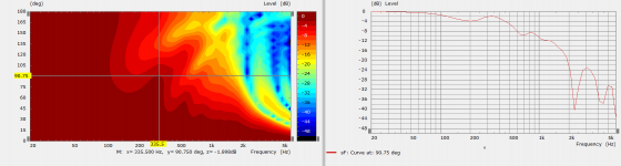
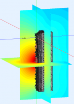
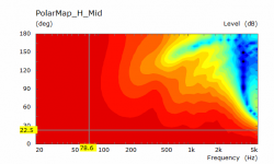
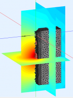
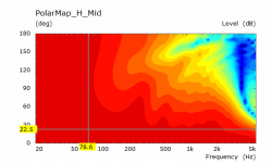
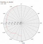
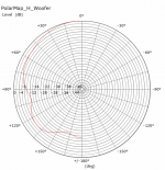
You are looking at the shape of the directivity and the relative intensity of the sound shown by colour from hot to cold, red to blue, high to low.
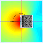
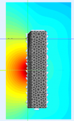
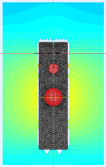
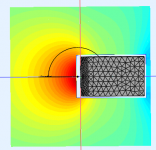
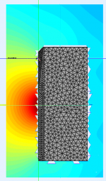
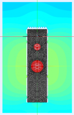
There are three planes drawn one through the woofer which can be seen from the top down and two others through the centre splitting the speaker in half and a plane through the center of the cabinet going up.
Where the shape expands out shows the shape of the lobe and how even that is. The nulls forming on the back corners of the cabinet are where there is negative interaction which is shaping the directivity at far off axis angles.
You are looking at the shape of the directivity and the relative intensity of the sound shown by colour from hot to cold, red to blue, high to low.
There are three planes drawn one through the woofer which can be seen from the top down and two others through the centre splitting the speaker in half and a plane through the center of the cabinet going up.
Where the shape expands out shows the shape of the lobe and how even that is. The nulls forming on the back corners of the cabinet are where there is negative interaction which is shaping the directivity at far off axis angles.
Ok.. I am just trying to understand here. So ideally we want that beam to be more even, in general, for all frequencies (at least for > 300Hz). We don't want the nulls and peaks to form. Nulls may not have been formed at this frequency if the height was more and depth was more. Basically, the dimensions should have been able to control control/shape the beam more.
In an ideal case, if the shape of the cabinet was a big sphere with diameter equal to cabinet height or an ellipsoid, would the radiation have had more evenness?
Even or smoothly changing is best. Peaks and dips are not ideal if they can be avoided. To EQ away an off axis peak you end up putting a dip in the on axis response. Avoiding it by acoustic design or crossing before it becomes a problem are decent solutions.Ok.. I am just trying to understand here. So ideally we want that beam to be more even, in general, for all frequencies (at least for > 300Hz). We don't want the nulls and peaks to form. Nulls may not have been formed at this frequency if the height was more and depth was more. Basically, the dimensions should have been able to control control/shape the beam more.
In an ideal case, if the shape of the cabinet was a big sphere with diameter equal to cabinet height or an ellipsoid, would the radiation have had more evenness?
Have a look here and the pages after at some simulations I ran on an ellipsoidal cabinet and my own fairly rectangular one. Even the addition of a 6mm chamfer on the front of the driver had a significant effect when combined.
The making of: The Two Towers (a 25 driver Full Range line array)
Even or smoothly changing is best. Peaks and dips are not ideal if they can be avoided. To EQ away an off axis peak you end up putting a dip in the on axis response. Avoiding it by acoustic design or crossing before it becomes a problem are decent solutions.
Have a look here and the pages after at some simulations I ran on an ellipsoidal cabinet and my own fairly rectangular one. Even the addition of a 6mm chamfer on the front of the driver had a significant effect when combined.
The making of: The Two Towers (a 25 driver Full Range line array)
Thanks a lot for pointing to this thread fluid.
")
I will try to understand the design tips and the simulations given there.
I think I will end up reading the whole of it pretty soon..
There is plenty of good stuff buried in there but it has grown long, happy readingI think I will end up reading the whole of it pretty soon..
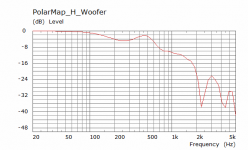
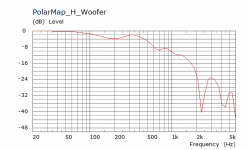
When I looked at the Horizontal directivity of the woofer next to it's response at different angles it became clear that the peaks seen are really formed by two nulls intruding either side. The effect is seen strongly at 90 degrees and looks just like edge and baffle diffraction. I think the 180 degree view and looking at a compressed frequency graph was throwing me off. The way the cabinet is now there is no edge treatment where the woofer is. I will run some other simulations to see if that has much effect at these frequencies as I was not expecting it to seem so pronounced. The observation fields show that there is no positive reinforcement just off axis nulls.
Attachments
Here are the results and observation fields for the 200mm deep version
Attachments
-
 400Hz200mmTD.png31.8 KB · Views: 1,126
 -
 400Hz200mmSide.png70.7 KB · Views: 75
 -
 400Hz200mmFront.png97.1 KB · Views: 75
 -
 400Hz200mmDiag.png75.6 KB · Views: 81
 -
 200mm Deep H Polar Curves Woofer.png23.6 KB · Views: 169
 -
 200mm Deep H Polar Mid Curves.png19.8 KB · Views: 177
 -
 200mm Deep H Polar Woofer.png35.8 KB · Views: 179
 -
 200mm Deep H Polar Mid.png29.9 KB · Views: 177
400mm deep, I need to look at these for a bit longer before I making any comment on what I think I am seeing. I decided against running the 100mm version as it seemed impractical, solving and preparing graphs eats time which could be better spent elsewhere.
Attachments
-
 400Hz400mmTD.png37.8 KB · Views: 1,113
 -
 400Hz400mmSide.png95 KB · Views: 71
 -
 400Hz400mmFront.png87.5 KB · Views: 68
 -
 400Hz400mmDiag.png97.8 KB · Views: 79
 -
 400mm Deep H Polar Curves Woofer.png22.5 KB · Views: 77
 -
 400mm Deep H Polar Mid Curves.png21.7 KB · Views: 91
 -
 400mm Deep H Polar Woofer.png36.8 KB · Views: 80
 -
 400mm Deep H Polar Mid.png30.1 KB · Views: 84
400mm deep, I need to look at these for a bit longer before I making any comment on what I think I am seeing. I decided against running the 100mm version as it seemed impractical, solving and preparing graphs eats time which could be better spent elsewhere.
Thanks a lot fluid for doing these comparisons
This is really interesting... I am just trying to write down what I understood looking at the plots based on my limited knowledge.
As you said earlier, this looks like diffraction is happening at low enough wavelengths. As we can see trends like peaks changing to nulls when the depth is doubled at a given frequency (for example around 350 Hz), it looks like a comb filtering is happening, with the varying depth, in turn, varying the delay that forms a part of the comb filter.
I am thinking it is the edges of the box at the back side and the top that is causing the main issues (abrupt change in acoustic impedance as the wave transitions suddenly from material of the box into free space, which is causing secondary waves to propagate from there and interfere with the waves produced by the driver at the off axis angles we are seeing main issues. As you had pointed out in an earlier post, there is definitely a vertical component involved as well, whose influence could be more visible in a vertical polar, I think.
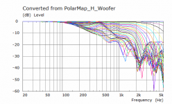
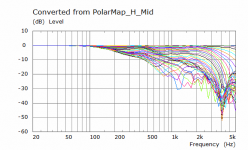
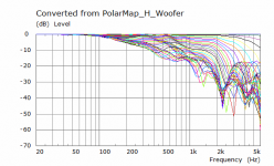
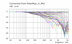
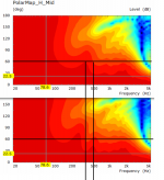
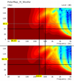
I have attached comparison plots of the midrange (Pic-1) and woofer (Pic-2) with this post. Top figure in each case is the 200mm depth and bottom one corresponds to the 400mm depth. The effect of a peak changing into a null-type of phenomenon is clearly visible in the polars of the mid driver. I think, since, in the mid driver's case, the effect of horizontal plane might be more significantly seen in these horizontal polars (as it is closer vertically to our observation point), the change in depth and the resulting discontinuity at the edge (at the back) is causing the major issue below the 500Hz range.
Another thing I am seeing is as the depth increases, the location of the main peaks are moving lower in frequency, which could be better for the mid, if we could smooth out the secondary peaks that come higher in frequency. It could also help the woofer somewhat, if we can smoothen the main peak.
Based on all this, I am thinking that instead of the really boxy shape I have, if I had smoother transitions/round overs/chamfers at all edges (back, top, everywhere possible), the difference in amplitudes of these peaks and dips might smooth out (I am thinking that is why revel M16 type or more "ellipsoidal" type enclosures that you had linked to in the other thread would be better instead of the rectangular box). I don't know if the edge treatment around the baffle would help with the woofer radiation at this lower in frequency, but it is definitely good to have smoother transitions everywhere, I think..
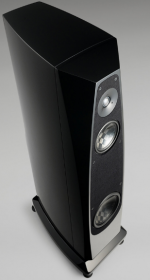
I am attaching some pics of the kind of cabinet shapes that might help us smooth out the peaks and dips. Even if all of these shapes may not be DIYable for me, at least if the hypothesis is correct, we might be be able to get better graphs with these kind of shapes/simplified versions of them I think..
Attachments
Last edited:
To me it seems that the difference between the 200 mm and 400 mm deep simulations are rather subtle. The frequency of the first peak/null is moved a bit, but the magnitude is not really affected. I cannot say which one I would prefer.
The entire region from 100 Hz to 400 Hz is going to be highly influenced by room boundaries, yes? I would think that the placement of the speakers and the position of the listener will be much more dominant than the diffraction effects off of the back of the cabinet.
I am not disputing that the cabinet depth will have some effect. But I am questioning whether a parameter as important as cabinet depth should be controlled by this effect. In this hypothetical case, going from 200 mm to 400 mm depth basically means nearly doubling the internal volume of the speaker, completely redesigning the bass alignment, probably using a different woofer(s).
j.
Or make a sub cabinet without changing anything to the design.
I know most would freak out as it seems a waste but you could then either introduce sand in the free space or incorporate amplifiers boards.
About the cabinet depth i find the 400mm to be more widespread in the horizontal plan, less focused than the other one. It may be of interest or not, depend on design target.
Yeah the responses are not exactly the same, some features seem to be similar and the deeper enclosure just shifts the whole feature set a bit lower in frequency. To the eye there is lot of similarity what happens when baffle is widened. More surface brings the lowest features even lower in frequency and the wiggle stays up until the driver size. In other words the problematic bandwidth widens, bigger physical construct just disturbs more (in relation to the transducer size of course) .
I was kind of hoping for the 10cm deep sim but I guess it would look somewhat the same, bit smoother (like the 20cm is bit smoother than the 40cm). I suspect roundovers on the back would smoothen it a bit more. But, not sure how these should be optimized. I guess there is some effect on the overall sound of the speaker system but it also depends on the positioning in the room as mentioned. Most difference seems to be outside listening window so it would be the early reflections that are affected.
I was kind of hoping for the 10cm deep sim but I guess it would look somewhat the same, bit smoother (like the 20cm is bit smoother than the 40cm). I suspect roundovers on the back would smoothen it a bit more. But, not sure how these should be optimized. I guess there is some effect on the overall sound of the speaker system but it also depends on the positioning in the room as mentioned. Most difference seems to be outside listening window so it would be the early reflections that are affected.
Last edited:
Thanks hifijim, krivium, and tmuikku
Thanks for the suggestions.
I was just thinking that the overall cabinet shape might help in smoothening the responses, if the shape is more rounded like, irrespective of the depth. Similar to how we take care in shaping the baffle, we may get better results by shaping the whole cabinet in 3D to smoothen out the acoustic impedance changes from cabinet to free space.
To my less experienced eyes, it seems like comb filtering at large off axis angles, caused by reflections/diffraction.
However, this is all my speculation and I will wait for fluid's perspective about this.
Just sharing this interesting site which among lots of other information has simple explanations and filters in general and specifically about comb filters (this may not be directlly applicable here, but i like filters in general, hence sharing.. ):
Intuitive Z-plane: Part 1 – Introduction – earfluff and eyecandy
Thanks for the suggestions.
I was just thinking that the overall cabinet shape might help in smoothening the responses, if the shape is more rounded like, irrespective of the depth. Similar to how we take care in shaping the baffle, we may get better results by shaping the whole cabinet in 3D to smoothen out the acoustic impedance changes from cabinet to free space.
To my less experienced eyes, it seems like comb filtering at large off axis angles, caused by reflections/diffraction.
However, this is all my speculation and I will wait for fluid's perspective about this.
Just sharing this interesting site which among lots of other information has simple explanations and filters in general and specifically about comb filters (this may not be directlly applicable here, but i like filters in general, hence sharing..
):Intuitive Z-plane: Part 1 – Introduction – earfluff and eyecandy
Last edited:
I can post the ABEC project if you want to solve it and prepare the graphs yourselfI was kind of hoping for the 10cm deep sim but I guess it would look somewhat the same, bit smoother (like the 20cm is bit smoother than the 40cm).
Yes for those that might not be familiar these are the measurements that make up the early reflections.Most difference seems to be outside listening window so it would be the early reflections that are affected.
Early Reflections
The early reflections curve is an estimate of all single-bounce, first-reflections, in a typical
listening room.
• Floor Bounce: 20º, 30º, 40º down
• Ceiling Bounce: 40º, 50º, 60º up
• Front Wall Bounce: 0º, ± 10º, ± 20º, ± 30º horizontal
• Side Wall Bounces: ± 40º, ± 50º, ± 60º, ± 70º, ± 80º horizontal
• Rear Wall Bounces: 180º, ± 90º horizontal
I agree with you particularly when the design is wide directivity in the mid and woofer. Avoiding the response shape seen in these sims won't come from a depth change alone.I was just thinking that the overall cabinet shape might help in smoothening the responses, if the shape is more rounded like, irrespective of the depth. Similar to how we take care in shaping the baffle, we may get better results by shaping the whole cabinet in 3D to smoothen out the acoustic impedance changes from cabinet to free space.
The word comb is usually used when there are lots of strong dips from cancellation close together as it resembles the fingers of a comb, but the mechanism that causes it is similar.To my less experienced eyes, it seems like comb filtering at large off axis angles, caused by reflections/diffraction.
At first glance that seems to be true but there are some more subtle aspects that are harder to spot that I made some graphs of below.To me it seems that the difference between the 200 mm and 400 mm deep simulations are rather subtle. The frequency of the first peak/null is moved a bit, but the magnitude is not really affected. I cannot say which one I would prefer.
Yes it is. I would argue that it can make sense to avoid a problem acoustically through design, particularly if to fix it electronically is hard.The entire region from 100 Hz to 400 Hz is going to be highly influenced by room boundaries, yes? I would think that the placement of the speakers and the position of the listener will be much more dominant than the diffraction effects off of the back of the cabinet.
This is all make believe and exploratory in simulation but in some practical cases your comment would be totally valid. This design was started as sealed and DSP and in that case alignments are irrelevant, as pointed out by krivium there are ways around that if the benefit was worth it. In this case I don't think it is.I am not disputing that the cabinet depth will have some effect. But I am questioning whether a parameter as important as cabinet depth should be controlled by this effect. In this hypothetical case, going from 200 mm to 400 mm depth basically means nearly doubling the internal volume of the speaker, completely redesigning the bass alignment, probably using a different woofer(s).
Here is my speculation/perspective. The more I look at it the less I like the 400mm deep version. There might be situations where a 400mm deep cabinet works with a narrower or wider baffle but I don't think it helps here. The 200mm version is smoother overall with less of a peak dip interaction.However, this is all my speculation and I will wait for fluid's perspective about this.
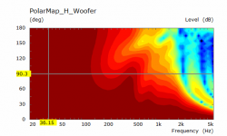
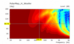
There is something interesting that occurs in the frequency range where the "eye" of the furthest off axis null occurs.
In the 200mm case this creates a nice super cardioid ish response around 600 to 700 Hz with 14dB or rear cancellation and even more around 150 degrees.
In the 400mm case this is a lumpy double null version of it
Attachments
I can post the ABEC project if you want to solve it and prepare the graphs yourself
Yes for those that might not be familiar these are the measurements that make up the early reflections.
Early Reflections
The early reflections curve is an estimate of all single-bounce, first-reflections, in a typical
listening room.
• Floor Bounce: 20º, 30º, 40º down
• Ceiling Bounce: 40º, 50º, 60º up
• Front Wall Bounce: 0º, ± 10º, ± 20º, ± 30º horizontal
• Side Wall Bounces: ± 40º, ± 50º, ± 60º, ± 70º, ± 80º horizontal
• Rear Wall Bounces: 180º, ± 90º horizontal
I agree with you particularly when the design is wide directivity in the mid and woofer. Avoiding the response shape seen in these sims won't come from a depth change alone.
The word comb is usually used when there are lots of strong dips from cancellation close together as it resembles the fingers of a comb, but the mechanism that causes it is similar.
At first glance that seems to be true but there are some more subtle aspects that are harder to spot that I made some graphs of below.
Yes it is. I would argue that it can make sense to avoid a problem acoustically through design, particularly if to fix it electronically is hard.
This is all make believe and exploratory in simulation but in some practical cases your comment would be totally valid. This design was started as sealed and DSP and in that case alignments are irrelevant, as pointed out by krivium there are ways around that if the benefit was worth it. In this case I don't think it is.
Here is my speculation/perspective. The more I look at it the less I like the 400mm deep version. There might be situations where a 400mm deep cabinet works with a narrower or wider baffle but I don't think it helps here. The 200mm version is smoother overall with less of a peak dip interaction.
There is something interesting that occurs in the frequency range where the "eye" of the furthest off axis null occurs.
In the 200mm case this creates a nice super cardioid ish response around 600 to 700 Hz with 14dB or rear cancellation and even more around 150 degrees.
In the 400mm case this is a lumpy double null version of it
Thanks a lot for your interpretations fluid..
This has been a really nice learning experience for me. I will try to go with a close to 20mm ish deep cabinet for this project I think. I will work out more details regarding the bass alignment. After thinking a lot I think I will go for a sealed cabinet alignment with this project. Anyway there is DSP. I can also always add a good subwoofer later if required. The Satori WO24P-8 driver gives a Qtc=0.707 sealed alignment with around 35L internal volume, which looks nice. Some people also suggest higher volumes like 50L sealed for this driver for better response. I will work out and finalize more details now.
I think you might have left a zero offI will try to go with a close to 20mm ish deep cabinet for this project I think.
FYI the 200mm is from the rear edge of the baffle you drew to the rear edge of the cabinet. Of the images of nice speakers you posted the Rockport is the only one to work with your current drivers although the TAD EVO is very slick. If you hold off a little longer I can try some different angles of facets and edge treatment around the woofer. These may combine to relieve some of the lumpiness. The Rockport has much more accute looking chamfers which can act like a larger round over.
The bigger the volume the less power is needed to drive the woofer, the Q and response can be shaped by DSP to be whatever you choose within limits of the driver.After thinking a lot I think I will go for a sealed cabinet alignment with this project. Anyway there is DSP. I can also always add a good subwoofer later if required. The Satori WO24P-8 driver gives a Qtc=0.707 sealed alignment with around 35L internal volume, which looks nice. Some people also suggest higher volumes like 50L sealed for this driver for better response. I will work out and finalize more details now.
I think you might have left a zero off
Of the images of nice speakers you posted the Rockport is the only one to work with your current drivers although the TAD EVO is very slick. If you hold off a little longer I can try some different angles of facets and edge treatment around the woofer. These may combine to relieve some of the lumpiness. The Rockport has much more accute looking chamfers which can act like a larger round over.
The bigger the volume the less power is needed to drive the woofer, the Q and response can be shaped by DSP to be whatever you choose within limits of the driver.
Sorry fluid.. I missed out a zero. I just looked at a scale and realized how that 200cm is not much of a depth. Maybe I will need to extend it a little more.. like 250 ish (definitely 400 is not needed)
Sure, I can hold off the project longer..
If you can run few more sims, I think many people including me will learn form it (Sorry that I might have already wasted a lot of your time with this so far)
I really like the looks of the Rockport cabinet..
With that 10inch Satori, I think that might be one of the better options for cabinet shapes available to me. If I had used something like multiple 7-8 inch woofers I would definitely have gone for a TAD cabinet-like looks Also a friend of mine has sort of agreed to build the cabinets for me and he has access to CNC. He can make the cabinet with curved back if required using multiple 4-6mm ply sheets. This might also help better than the current boxy shape I have at the back
If nothing else, it will look better I will be looking for an internal volume of something around 35L plus for woofer box and more if the cabinet dimensions permit and then try to use DSP to control the alignment.
200cm is quite some depthI just looked at a scale and realized how that 200cm is not much of a depth.
200mm or 20cm If it wasn't interesting I wouldn't have offered. It has taken time but I don't consider it wasted.If you can run few more sims, I think many people including me will learn form it (Sorry that I might have already wasted a lot of your time with this so far)
I'll try some basic things first to try and confirm what is going on then look at something more Rockport like.I really like the looks of the Rockport cabinet..
- Home
- Loudspeakers
- Multi-Way
- A 3 way design study