Well again, the claim is the surround causes an issue with HD and IMD. And that may be true enough, but the proof is in the pudding as they say, so compare the HD and IMD of those two drivers at Hificompass's website. Then you can see if it is actually a problem or not.
Well again, the claim is the surround causes an issue with HD and IMD. And that may be true enough, but the proof is in the pudding as they say, so compare the HD and IMD of those two drivers at Hificompass's website. Then you can see if it is actually a problem or not.
Thanks Augerpro. I could find the Harmonic distortion plots and see that CAC might perform slightly beter between these drivers. I looked around for IMD results on CAC driver but couldnt find it. I could see the Wavecor WF120BD03 driver's IMD results here:
Wavecor WF120BD03 | HiFiCompass - всё для акустических систем и не только
I have some confusion about how to read and interpret it. Here is my current understanding. I took a look at the 3mm (30hz+255hz) results for IMD. From what I am seeing there what I am understanding is that if we excite this driver with a 30 hz and 255 Hz tones simultaneously at an amplitude level such that the driver will be going into 3mm excursion state, in the ideal case only those two tones should be reproduced. but we can see from the spectrum that a lot of other tones (distortion products probably ) are reproduced by the driver. This is supposed to be bad. Probably the ones which are to the right of 300 Hz is more bad in our application since the high pass filtering for the mid will attenuate the lower frequencies below 300Hz depending on its slope. I see that the highest distortion product itself is about 30dB lower in level compared to the main tones (30 and 255). This looks like good. But I have no idea how all these values will sound like.
Please correct me if my interpretations are wrong.
Troels Graveson has a good writeup on surround dips and associated harmonic peaks. His conclusion seemed to be that it was not very audible but more of a visual distraction. The satori drivers have one of the worst cases of it but no one is complaining too much about the sound.
If you read the Purifi driver review at hificompass there is a description of the intermodulation test he does there and a link to a paper on distortion by purifi.
Harmonic distortion is not very well correlated with sound quality. I would spend more time looking at the impedance response and the CSD or waterfall graph. Frequency response can be corrected but the stuff in those graphs cannot.
To simulate the baffle a step file would-be helpful. PM me and we can work it out. If Brandon has physical measurements of the tweeter or Ath input then I can include the dome and waveguide for a better simulation.
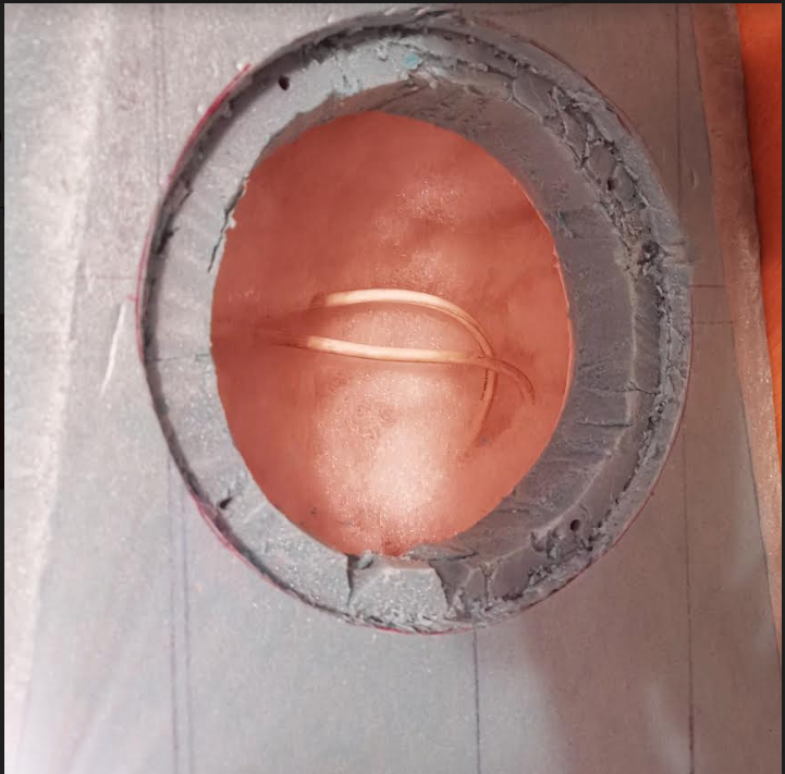
Vineeth, midrange driver is sensitive to baffle cutout contour on the inside. Straight cutout is prone to standing waves. Chamfering is highly recommended!
Regarding the discussion about best mids, I understand different opinions and lack of definitive consensus regarding audibility of harmonic and IMD, as well as "ringing". Funny thing, that Purifi 4" has rather poor performance in upper range... Abrupt change in directivity like it has, is not what I could accept from a midrange driver!
Regarding the discussion about best mids, I understand different opinions and lack of definitive consensus regarding audibility of harmonic and IMD, as well as "ringing". Funny thing, that Purifi 4" has rather poor performance in upper range... Abrupt change in directivity like it has, is not what I could accept from a midrange driver!
Vineeth, midrange driver is sensitive to baffle cutout contour on the inside. Straight cutout is prone to standing waves. Chamfering is highly recommended!
Regarding the discussion about best mids, I understand different opinions and lack of definitive consensus regarding audibility of harmonic and IMD, as well as "ringing". Funny thing, that Purifi 4" has rather poor performance in upper range... Abrupt change in directivity like it has, is not what I could accept from a midrange driver!
Thanks Juhazi for pointing Troels's article to me earlier. I will definitely have a generous chamfering on the inside contour regardless of the mid driver that I will use. The other interesting thing I noted regarding this is that in the satori drivers, the backside is tapering in dimensions and magnets slowly get out of the way of airflow to the back wheres in the regular CAC kind of drivers, this tapering is much less. Maybe this aspect may have got something to do with its suitability in deep baffles. Just thinking aloud.. 🙂
Last edited:
Peerless NE drivers have very small neo magnets, which is one reason why I chose NE95 as first choice fo my AINO dipoles. Sadly in OB even that was too much... Perhaps it ws the large spider?
What I don't like about NE series, is the deep cone profile, making directivity change sharp.
https://audio-hi.fi/download/pdf/Peerless_Vifa_NE149W-08_woofer.pdf
What I don't like about NE series, is the deep cone profile, making directivity change sharp.
https://audio-hi.fi/download/pdf/Peerless_Vifa_NE149W-08_woofer.pdf
Peerless NE drivers have very small neo magnets, which is one reason why I chose NE95 as first choice fo my AINO dipoles. Sadly in OB even that was too much... Perhaps it ws the large spider?
What I don't like about NE series, is the deep cone profile, making directivity change sharp.
https://audio-hi.fi/download/pdf/Peerless_Vifa_NE149W-08_woofer.pdf
Thanks Juhazi. 🙂
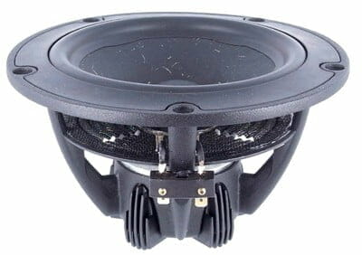
I had initially looked around for the NE149 driver but couldn't find it anywhere in India. We had only NE95, NE123, NE180, NE225 and NE315 available here. Hence I started to look around for other drivers and saw SB15CAC being recommended by many experienced people including hifijim. For example this is a thread where SB15CAC mid is used and I see good opinion about it. It also depends on a good implementation and I am a beginner. So I will try to do my best in this.
The Travelers - New Year, New Design -
Techtalk Speaker Building, Audio, Video Discussion Forum
I am kind of thinking that only if I get an MR13P for reasonable price, I will change the mid. Otherwise, I will proceed with this mid for this project.
Last edited:

Thanks to augerpro I am off to a good start. I was able to reduce the mesh size quite considerably and still come up with the same answer which will make simulating the whole thing much more feasible. Solve time dropped from 36 minutes to 1:45 🙂
Awesome 🙂 🙂
Thanks a lot Augerpro and Fluid for helping out.
Eagerly looking forward to more results 😀 🙂
Simulated results will take a bit longer here is the next step in the journeyEagerly looking forward to more results 😀 🙂
Driving elements, for now flat discs that represent the Sd of the drivers centred where the real drivers would be on the baffle
Simplified CAD model of the baffle and cabinet
Attachments


Wow.. 🙂🙂 Thanks.🙂
This is very exciting for me. 🙂
In the meanwhile, I am learning bit by bit about drawing in fusion 360 and also about many related aspects like impact of width and depth of cabinet on directivity by reading related threads.
This is very exciting for me. 🙂
In the meanwhile, I am learning bit by bit about drawing in fusion 360 and also about many related aspects like impact of width and depth of cabinet on directivity by reading related threads.

When you put them together you get this
Now its looking really cool.. 😀😀
I have to troubleshoot an issue that has occurred when placing the waveguide in a baffle so that part has stalled for now.
Here are some preliminary horizontal directivity responses for the mid and woofer when simulated as flat discs of corresponding Sd and driven with constant acceleration. Measurement point is at the tweeter axis.
As theses are simulated 0 to 180 degrees some of the far off axis responses dominate the view of the polar plot. The peaks that pop out show some areas of concern for the 200 to 500Hz range in the woofer. If these were gone the directivity would be more even.
The mid looks good if it's crossed over high enough.
Attachments


I have to troubleshoot an issue that has occurred when placing the waveguide in a baffle so that part has stalled for now.
Here are some preliminary horizontal directivity responses for the mid and woofer when simulated as flat discs of corresponding Sd and driven with constant acceleration. Measurement point is at the tweeter axis.
As theses are simulated 0 to 180 degrees some of the far off axis responses dominate the view of the polar plot. The peaks that pop out show some areas of concern for the 200 to 500Hz range in the woofer. If these were gone the directivity would be more even.
The mid looks good if it's crossed over high enough.
Thanks Fluid. How do we try to understand what is happening in this scenario.
For example if the simulation is happening in free space, all drivers trying to radiate into 4pi space, how do we explain specifically about the first peak off-axis which occurs around 350Hz (approx. 1m wavelength) and a secondary peak with lower amplitude happening about 700 Hz (approx. 50 cm wavelength).
The only dimensions of the cabinet I can think of (in a horizontal plane) that relates to these kind of wavelengths is cabinet depth(side-1: 35.5cm) + baffle width (back: 28cm) + cabinet depth (side-2: 35.5cm), the total of which comes close to 1m.
Is it possible that an approx. 1m long wave, which comes back after traveling around the cabinet (side-1 + back + side-2) and constructively interferes with waves of same frequencies emitted by the driver itself and causes that first peak around 350Hz?
(The relative phase shifts of the waves around this wavelength causing the interference magnitude to decrease around the peak)
Similarly a wave of twice the frequency (the 50cm long one) does the same thing and causes the peak around 700Hz but diminished in amplitude due to the relatively less energy coming back after wrapping around the cabinet?
I dont know if the above explanation makes sense. I was just trying to come up with some reason for above behavior in this simplified setup. 🙂
Thanks
Vineeth
Last edited:
The peaks that pop out show some areas of concern for the 200 to 500Hz range in the woofer. If these were gone the directivity would be more even.
Right, you need a ~36" wide baffle for proper BSC = 10^6/[36x180] = ~154 Hz.
That is a good question 🙂 I will create some observation fields so that you can see the wavefront movement around those frequencies which should make the reason clearer.Thanks Fluid. How do we try to understand what is happening in this scenario.
This is a free space simulation. There will be a transition from 2pi based on the baffle width to fully 4pi where the width and depth interact in the transition.
The measurement point being at the tweeter level also has a vertical component as both mid and woofer are below and you can see the black arc in the mesh drawing that shows the direction of the measurement arc.
So whilst it is horizontal directivity it is not centred around each driver, which would look better, but not necessarily be an accurate representation of how the speaker would be heard.
All of the peaks and dips come from specific distances or combinations of them much like you tried to hypothesize. Working out which ones is not always easy and it won't just be horizontal. The fields should help.
Yes they are, they don't have to be but not many people are used to looking at non normalized polar charts. I tend to find the non normalized SPL curves at specific angles to be more readable but I haven't sorted all of the observation scripts out for this model yet.Looks like fuid'd response charts in post #134 are normalized to 0-axis, right?
That is a good question 🙂 I will create some observation fields so that you can see the wavefront movement around those frequencies which should make the reason clearer.
This is a free space simulation. There will be a transition from 2pi based on the baffle width to fully 4pi where the width and depth interact in the transition.
The measurement point being at the tweeter level also has a vertical component as both mid and woofer are below and you can see the black arc in the mesh drawing that shows the direction of the measurement arc.
So whilst it is horizontal directivity it is not centred around each driver, which would look better, but not necessarily be an accurate representation of how the speaker would be heard.
All of the peaks and dips come from specific distances or combinations of them much like you tried to hypothesize. Working out which ones is not always easy and it won't just be horizontal. The fields should help.
I tried to study a little more about this. I tried to see if I can see similar behavior in VituixCAD by using the diffraction tool to generate the frequency responses to off-axis angles as shown in attached pic -1 with the woofer radiation viewed from tweeter axis 3m away. But I saw only smooth variations in directivity (Maybe because the VituixCAD modeling doesnt take into account the effects of cabinet width and depth?)
Next I looked at the 3 way example project given in VituiCAD website: VituixCAD Loudspeaker simulator
I have attached it in pic-2, I think I can see in the real measurements of the woofer response that is given in it, the kind of phenomenon that we are seeing here (peaks around 300-500Hz and 700-1000Hz). 🙂
So what is happening seems like the interaction of the depth and width of the cabinet during the baffle diffraction step transition for the woofer and similarly for the mid driver as you and others have been pointing out.
If this is the case, is there a specific combination/ratio of dimensions that will help us see smoother directivity transition at these lower frequencies (wider baffle + less deep cabinet?). Or we have to live with this kind of response if I retain the cabinet dimensions as I have currently. The other question I have is, audibly, what could be kind of impact
of this kind of peaks in the response since it looks like the kind of frequencies below which the room takes over. Also I have heard people saying that the 200-400 Hz frequencies are very important perceivably in setting audible levels for the rest of the spectrum etc. I don't know much about any of these yet. 🙂
Just trying to write down some thoughts here.. 🙂
Attachments


Last edited:
- Home
- Loudspeakers
- Multi-Way
- A 3 way design study