After a lot of hard work by a friend


And the result is 😀


I think it looks really nice now.. 😀
If only the performance could match the looks now.. 😀
And the result is 😀
I think it looks really nice now.. 😀
If only the performance could match the looks now.. 😀

They are home 😀


To they are ready for measurements 😀

Back of the coaxial driver filled with 55mm thick melamine foam covered with a sock cloth ring (for now). This is for the cardioid midrange 🙂


To they are ready for measurements 😀
Back of the coaxial driver filled with 55mm thick melamine foam covered with a sock cloth ring (for now). This is for the cardioid midrange 🙂
Some starter measurements 😀
Woofer free air vs in box impedance measurements

Woofer nearfield + impedance in box (not baffle step adjusted)

Sica mid and tweeter impedance (in box)

This much is all I have got today.. The farfield measurements will tell us whether the cardiod midrange works (or not)... Waiting for that exciting/ heartbreak moment 😀
Whatever happens, I really love the looks of this speaker 😀
Woofer free air vs in box impedance measurements
Woofer nearfield + impedance in box (not baffle step adjusted)
Sica mid and tweeter impedance (in box)
This much is all I have got today.. The farfield measurements will tell us whether the cardiod midrange works (or not)... Waiting for that exciting/ heartbreak moment 😀
Whatever happens, I really love the looks of this speaker 😀
Last edited:
Very nice, big plus for the shape idea and execution...👍
Please show us horizontal and vertical measurements with completely open back side of coax and if you can - only with left and right opening....I mean to block upper part above and below coax.
It would be interested to see dispersion difference between all 360 degrees leaking behind the driver and only left and right (like dutch n dutch is leaking just a little bit on sides...).
I hope you will be satisfied with sound. 🙂
Tell your friend who painted them he/she did an amazing job. Lines in the paint reflections are sharp and clean. I'm certain they will sound great because you simulated them. In my very limited experience simulations do a great job. However, your design is a lot more complex than anything I've done so you'll have to spend time on working out the resistance media in addition to the crossovers before you're completely happy with them.
Also, they're visually stunning. You'll have a lot of fun listening to those and showing them off to your friends.
Also, they're visually stunning. You'll have a lot of fun listening to those and showing them off to your friends.
The speakers are measured (horizontal polars 0 to 180 degrees)

Mid driver (measurements beyond 160 degrees are probably garbage)

tweeter

Woofer

Now a first attempt crossover (reference axis is 10 degrees off axis)


I think it is all working as expected.. 😀 😀
Mid driver (measurements beyond 160 degrees are probably garbage)
tweeter
Woofer
Now a first attempt crossover (reference axis is 10 degrees off axis)
I think it is all working as expected.. 😀 😀
The progress you have made in the last couple of years is great to see 🙂
Great project!
Is there a resonance around 5k in the mid? Could be audible depending on how severe it is?
You might be interested in investigating high drive impedance to see what it does with distortion, I have played around with this recently (mids on two pair of speakers -active and passive XO), and it seems both measured and subjective performance were improved.
I did one more iteration of the crossover. Here is it
Reference axis is 20 degrees off axis


Now I have a few questions. 🙂
1) What should be the target for optimizing the responses? (The application is relatively near to mid-field listening)
2) Is it possible to remove that excess group delay bump of 2ms around 300Hz? (I have heard that getting it under 2ms above 100Hz is good?)
3) Can we improve the timing response curves?
Any improvement to frequency response curves is always welcome while doing the above 😀
I have attached the vituixcad project files here (due to the large file size): https://drive.google.com/file/d/1Ynzzac-tJfbAaezGuehd63ZGNzwcVu4C/view?usp=sharing
Please take a look at it.
I am also wondering about a passive crossover version of the above speaker. Given the relatively less EQ needed, I think it is a possibility.. 🤔
Reference axis is 20 degrees off axis
Now I have a few questions. 🙂
1) What should be the target for optimizing the responses? (The application is relatively near to mid-field listening)
2) Is it possible to remove that excess group delay bump of 2ms around 300Hz? (I have heard that getting it under 2ms above 100Hz is good?)
3) Can we improve the timing response curves?
Any improvement to frequency response curves is always welcome while doing the above 😀
I have attached the vituixcad project files here (due to the large file size): https://drive.google.com/file/d/1Ynzzac-tJfbAaezGuehd63ZGNzwcVu4C/view?usp=sharing
Please take a look at it.
I am also wondering about a passive crossover version of the above speaker. Given the relatively less EQ needed, I think it is a possibility.. 🤔
@Rallyfinnen: Thanks for the suggestion.
I will look at the Purifi series notch application as well and see if it improves anything in this case 🙂
I will look at the Purifi series notch application as well and see if it improves anything in this case 🙂
I recently removed the 1k-20k sloping filter on my speakers that I had implemented since @hifijim came up with his PEQ suggestion. It took me so long to get accustomed to bass after room correction. I would also suggest to start from a flat (LW / design axis) response.
Have you ever considered trying a linear phase crossover between the coaxial drivers? You ought to have the tools for it, and that high up it shouldn’t cause any delay issues.
You are already inside the window of paint by numbers to get a reasonable response. Try some different options and listen to the differences. There still seems quite a bit of dipole in the mid response.Now I have a few questions. 🙂
1) What should be the target for optimizing the responses? (The application is relatively near to mid-field listening)
Make the slope of the crossover less steep in that region. Zoom in on the filter and phase response window and you can see where they line up.2) Is it possible to remove that excess group delay bump of 2ms around 300Hz? (I have heard that getting it under 2ms above 100Hz is good?)
Passively or actively you can invert the tweeter, use a single order filter combined with a deep notch (below or above) the crossover to steepen it up further away from Fc. That way the tweeter can rise up at the same time as the mid and step will look better. This is what Joe Rasmussen does in the Elsinore. The filter will then look a lot like an elliptic. Use a lower slope crossover from woofer to mid. It is unlikely that either of these will make the frequency response better. Or go linear phase, that does work better with fully complementary acoustic slopes, to cancel preringing so sloping the response down breaks that somewhat.3) Can we improve the timing response curves?
Any improvement to frequency response curves is always welcome while doing the above 😀
Vineeth,
Looking good!
Would you please post measurements limited to 90 degrees? It might help me see what's happening orthogonal to the on-axis.
Here's something i did earlier this year, but it's not cardioid:


.
Looking good!
Would you please post measurements limited to 90 degrees? It might help me see what's happening orthogonal to the on-axis.
Here's something i did earlier this year, but it's not cardioid:
.
Motivated by @fluid's comment about hints of dipole radiation in the mids, I went and measured the mid again (0 to 180 degrees horizontal polar). As I suspected some measurements from yesterday, beyond the 150 degrees angle was garbage. Here is a snapshot of today's polars for the mid. It looks much cleaner now than yesterday's and more cardioid than dipole 🙂

Directivity based on Measurements from today above responses (measurements are 4.4ms gated)

Measurements from yesterday showing more energy at large off axis angles (measurements are 4.4ms gated)

Directivity based on Measurements from today above responses (measurements are 4.4ms gated)
Measurements from yesterday showing more energy at large off axis angles (measurements are 4.4ms gated)
Attachments

WIth the new measurements I changed the crossover from yesterday slightly and it looks like this


@tktran303: Here are the polars restricted to 90 degrees. Is this what you meant?

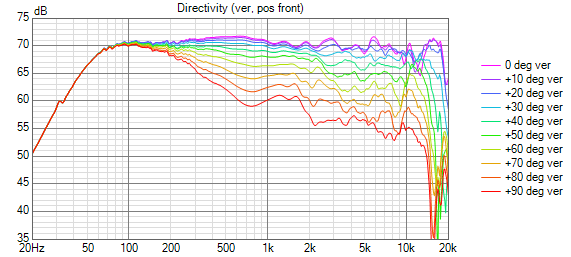
Now I am going to explore all the tricks that @fluid mentioned for response shaping and timing adjustments 🙂
@tktran303: Here are the polars restricted to 90 degrees. Is this what you meant?
Now I am going to explore all the tricks that @fluid mentioned for response shaping and timing adjustments 🙂
Attachments

Even though it's not cool anymore, I quite like to look at the cartesian polar plot to "see" the shape of the pattern. It can be tricky to find the slider below the window in Vituix to move the frequency of the plot.Here is a snapshot of today's polars for the mid.
Here are a few polar plots of the mid driver using measurements from today.
I tried to take it at roughly every 100Hz from 200Hz till 1kHz and roughly every 500kHz thereafter till about 2.5kHz:


I tried to take it at roughly every 100Hz from 200Hz till 1kHz and roughly every 500kHz thereafter till about 2.5kHz:
- Home
- Loudspeakers
- Multi-Way
- A 3 way design study