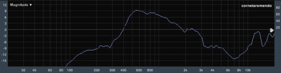
Measurement that close to the horn mouth will be a bit "off", but the general -12dB per octave rolloff is to expected.I took the measurement on the central axis of the horn, positioning the microphone right after the end of it. 1/12 magnitude smooth.
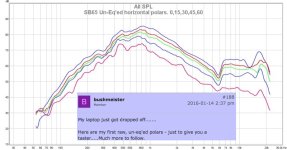
Corporatemisfit's measurement looks closer to bushmeister's than yours:From what I could see in corporatemisfit's measurement, this same pattern that I could observe in my measurements was repeated. Is this normal or is there something that could've been done wrong?
Throat details, driver differences, measurement distance and mics, smoothing, and room surroundings all play a part in what you will see.
The phase wraps in your screen shot (lost count after 5760 degrees
") ) show the delay found (or applied) is wrong.
) show the delay found (or applied) is wrong.That shouldn't affect the frequency response portion of the graph, but you will want to sort that issue out before working on the crossover
Art
Attachments
There has been some effort around mating the 2.5" driver to the horn mouth, in order to smooth a notch. There was some success here, with felt + epoxy putty for bushmeister and a 3d printed adapter for xrk971 (on different horns). Part of what is going on is the horns are 1.4" which is a standard size for compression drivers. The 2.5" drivers are too large to fit directly to the horn opening.
So if you could magic up a horn (print / make / modify / etc) with whatever properties you wanted, is it better to have the mouth a bit small and implement some transition to narrow it before it opens up again? Or would it be better to have a horn that was wide enough to start just exactly around the outside of the driver's surround?
I've read a bunch of this thread, there's quite a lot here. I do recall seeing some discussion of this geometry.
options that I'm considering, but haven't seen discussed
Finally, one option is "we don't know, it just ended up this way"...
Can anyone say it's one of these things, or I have misunderstood and it's something else?
So if you could magic up a horn (print / make / modify / etc) with whatever properties you wanted, is it better to have the mouth a bit small and implement some transition to narrow it before it opens up again? Or would it be better to have a horn that was wide enough to start just exactly around the outside of the driver's surround?
I've read a bunch of this thread, there's quite a lot here. I do recall seeing some discussion of this geometry.
- there are phase plugs and compression, these small FR drivers are not compression drivers and probably that is not best for them (this would be extreme narrowing)
- substantial narrowing but with no phase plug, this would make a band pass, I think, and is probably not desirable here
- some narrowing (maybe a slot, so it's narrow but maintains cross sectional area) can be used to create diffraction to spread HF coverage, but this might sound bad. Some horns do this in stock form, but I think not the two prime examples in this thread.
- just a bit of narrowing, with a smooth non-diffracting profile (and or damping material) to prevent a discontinuity and internal reflections. Just an interface between these two shapes, if the horn and the driver were the same diameter this would be unnecessary.
options that I'm considering, but haven't seen discussed
- the driver surround makes a noise we don't like, so we block it a bit. But the diaphragm output sounds good and it escapes. So the narrowing is a useful acoustic feature.
- Driver Sd only includes a portion of the surround. The narrowing helps the horn mate to exactly the Sd of the transducer. So the narrowing is a useful acoustic feature.
Finally, one option is "we don't know, it just ended up this way"...
Can anyone say it's one of these things, or I have misunderstood and it's something else?
Thanks for the answers.
Forgive me, I forgot to mention that I haven't connected the speakers yet, so this measurement is only from the sb65wbac25 in full range connected to the horn, so I haven't applied delay, crossover or anything yet.
Art, knowing that, should I still worry about the phase before proceeding?
Forgive me, I forgot to mention that I haven't connected the speakers yet, so this measurement is only from the sb65wbac25 in full range connected to the horn, so I haven't applied delay, crossover or anything yet.
Art, knowing that, should I still worry about the phase before proceeding?
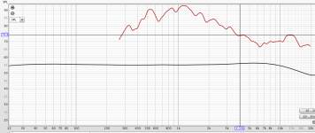
Right, filtering is needed to flatten the part below 2 khz. shelfing filter or so. Multi point horns use that also.Wow! Nice work! I think the falloff above 3k5 is normal and EQ is needed. It’s a shame to attenuate that else it would be very high sensitivity. But works well to match the bass level.
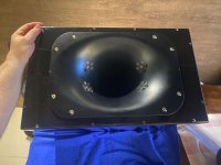
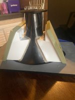
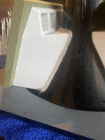
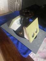
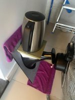
Some progress...
Attachments
-
 WhatsApp Image 2024-06-21 at 17.43.41 (4).jpeg145.7 KB · Views: 46
 -
 WhatsApp Image 2024-06-21 at 17.43.42.jpeg120.4 KB · Views: 44
 -
 WhatsApp Image 2024-06-21 at 17.43.41 (3).jpeg110.6 KB · Views: 47
 -
 WhatsApp Image 2024-06-21 at 17.43.41 (2).jpeg107.1 KB · Views: 40
 -
 WhatsApp Image 2024-06-21 at 17.43.41 (1).jpeg159.5 KB · Views: 41
 -
 WhatsApp Image 2024-06-21 at 17.43.41.jpeg130.6 KB · Views: 46
Adam,Part of what is going on is the horns are 1.4" which is a standard size for compression drivers. The 2.5" drivers are too large to fit directly to the horn opening.
So if you could magic up a horn (print / make / modify / etc) with whatever properties you wanted, is it better to have the mouth a bit small and implement some transition to narrow it before it opens up again?
The mouth of a horn is the large end, the throat is where the driver is attached.
Small horn throats are desirable for extended smooth high frequency response, large driver Sd and excursion is required for low frequency output. Compression drivers use phase plugs to solve that problem, but the greater excursion and lower motor strength of a full range driver eliminate that option.
A driver to throat reduction adapter is required for the compromise.
A throat reduction creates an acoustical bandpass filter, reducing high frequency response.
The SB65 throat reduction adapter with the felt ring as bushmeister or Corporatemisfit use in post # 1833 appear to work well.
A larger throat would compromise the upper frequency response. A driver with only 1.4" diameter would not have enough output capability to keep up with the 2 woofers.Or would it be better to have a horn that was wide enough to start just exactly around the outside of the driver's surround?
Art
It was apparent the measurement was the SB65 only.Forgive me, I forgot to mention that I haven't connected the speakers yet, so this measurement is only from the sb65wbac25 in full range connected to the horn, so I haven't applied delay, crossover or anything yet.
Art, knowing that, should I still worry about the phase before proceeding?
No need to worry about the phase before proceeding, but you will have to figure out how to properly set the measurement system to eliminate the excessive phase wraps before proceeding with EQ and crossover settings.
Art
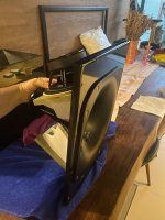
@viniciusv well done!. You project is looking good!
Looking at the pictures it appears that the felt lining around the edge of SB65 is thicker than 2mm. The reason I settled on the 2mm thickness was to ensure that the felt did not touch the roll surround of the SB65.
The felt touching the roll surround may have an impact on the distortion levels and frequency response.
Regarding the frequency response, this is normal when horn loading a speaker. You do need some form of DSP to equalise the response.
With my combination of SB65/XT1464 I get approx. 20db of acoustic gain between 460hz and 1100hz. Then a 10db and octave roll off to 4400hz. It is relatively easy to equalise this back to flat.
The benefit of this approach is that I use 20db less amplifier power and associated speaker excursion in the critical lower octave of the driver.
Looking forward to watching your progress!!
- Home
- Loudspeakers
- Multi-Way
- A Bookshelf Multi-Way Point-Source Horn