That Zero-Zone PCB is based on a topology that used to be called a "Ring of Three".
What about a Ring of Three?
The first stage is a common cathode voltage amplifier.
That's RC-coupled to the second stage common cathode voltage amplifier.
The 2nd stage is DC-coupled to a cathode follower.
The CF drives the feedback loop with a lower impedance than would be available from the plate of the 2nd stage triode.
That circuit could be done using 12AU7 tubes and it could turn out to be pretty good.
If the purpose of this thread is to find the best route to an ECC82 preamp, then yes, I agree! A 'Ring of Three' using 12AU7 tubes is a good route to take. A stereo line stage will require three 12AU7s, or one could substitute a MOSFET follower for the 3rd stage cathode follower, which would be an improvement.
View attachment 1053892
Actually, I did not know this topology so-called "ring of three" (I think it's a technical jargon).
Anyway I reminded me of the Marantz 7 phono preamp, which apart from differents tubes there has a circuit analogies...isn't it?
Attachments
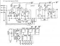
If you look at the line stage part of that Marantz 7c schematic, you can see that it's a Ring of Three but the NFB is taken off the plate of V2 instead of from the cathode of V3. One has to ask why, since that's a worse way to do it. But there it is.

The NFB is applied through the 82k resistor from the plate of V2 (grid of V3). Marantz probably did it this way so they wouldn't need to use a large coupling capacitor, which would have been really expensive back in 1958.
Today, we could do it like this:

Yes, that is a 27k resistor as the cathode load for V3
--
The NFB is applied through the 82k resistor from the plate of V2 (grid of V3). Marantz probably did it this way so they wouldn't need to use a large coupling capacitor, which would have been really expensive back in 1958.
Today, we could do it like this:
Yes, that is a 27k resistor as the cathode load for V3
--
The ring of three is an interesting concept and one that has been copied in the semiconductor world. The main problem with it is stability because you have at least three zeros in the loop which means you need to take great care with LF stability (among other things). The reason this is a problem is because it makes it difficult to ensure the circuit is unconditionally stable except at a given closed loop gain (or a narrow band of gains). If you want stable gain over a wide range of gain values e.g. RIAA or a mic pre for example you need to do something to address this issue. LF stability is not usually an issue in the semiconductor case as all three zeros can usually be eliminated by dc coupling but this is much harder to achieve in tube circuits. The first change you can make is realize that the CF only contributes a low output impedance and unity gain but the cost is an extra zero. You can eliminate the zero between V2 and V3 by rearranging the last two tubes as an SRPP. You get the same loop gain with one less zero and a true push pull output that easily exceeds the drive capability of the CF at the same quiescent current.
Eliminating the zero between V1 and V2 is very difficult but it is possible to eliminate the one in the NFB network by dc coupling the SRPP output to the cathode of V1 and running V1 at a much higher cathode voltage.
Cheers
Ian
Eliminating the zero between V1 and V2 is very difficult but it is possible to eliminate the one in the NFB network by dc coupling the SRPP output to the cathode of V1 and running V1 at a much higher cathode voltage.
Cheers
Ian
Wouldn't DC-coupling V2 and V3 get rid of at least that one zero?
And isn't an SRPP only balanced into a narrow range of load impedance?
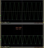
I do see what you mean about low frequency stability (see circuit in the picture).

There is a bump in response around 1Hz at the plate of V1, as it compensates for the loss of gain down there caused by the poles made by C1/R5 and C2/R11. In the simulation (er-hem), C6 added at the input makes the amp response -3dB at 1.3Hz, with no bumps in response above that. Increasing the value of C3 to 100uF helps a bit. I'll bet increasing the value of C4 would also. I'd guess that adding a regulated PSU with super-low output impedance would help even more, but now things are getting complex...
And isn't an SRPP only balanced into a narrow range of load impedance?
I do see what you mean about low frequency stability (see circuit in the picture).
There is a bump in response around 1Hz at the plate of V1, as it compensates for the loss of gain down there caused by the poles made by C1/R5 and C2/R11. In the simulation (er-hem), C6 added at the input makes the amp response -3dB at 1.3Hz, with no bumps in response above that. Increasing the value of C3 to 100uF helps a bit. I'll bet increasing the value of C4 would also. I'd guess that adding a regulated PSU with super-low output impedance would help even more, but now things are getting complex...
Last edited:
I'm having a hard time picturing this.You can eliminate the zero between V2 and V3 by rearranging the last two tubes as an SRPP.
Eliminating the zero between V1 and V2 is very difficult but it is possible to eliminate the one in the NFB network by dc coupling the SRPP output to the cathode of V1 and running V1 at a much higher cathode voltage.
The output of the SRPP (V2 on top of V3) is the plate of the bottom triode (V3). That will sit at 1/2 of B+, so about 130V DC. How could you possibly DC-couple that to the cathode of V1, with V1 supplying any gain at all?
Hmmm... Looking at this again...

Sid Smith was a pretty smart guy. Taking the NFB off from right after the coupling cap after the V2 plate not only saves the cost of a big DC blocking cap, it also sidesteps the added pole inside the NFB loop.
NOT DC-coupling V2's plate to V3's grid allows V3's grid leak resistor to be bootstrapped to a very high value, so now the DC blocking cap to the grid of V3 can be a very small value (0.01uF in the case of the Marantz 7c line stage).
Now with the cathode follower's Cout outside of the feedback loop, it can be used to roll off whatever LF resonances there might be at subsonic frequencies.
That's interesting. Let's model it. I'm just going to put this here because I think it's interesting.

Notice that with the big (but not crazy big) cap values I've used, there is now no LF bump anywhere in this circuit, and the NFB loop can be DC-coupled.
Yup. Sid Smith was one smart cookie.
Sid Smith was a pretty smart guy. Taking the NFB off from right after the coupling cap after the V2 plate not only saves the cost of a big DC blocking cap, it also sidesteps the added pole inside the NFB loop.
NOT DC-coupling V2's plate to V3's grid allows V3's grid leak resistor to be bootstrapped to a very high value, so now the DC blocking cap to the grid of V3 can be a very small value (0.01uF in the case of the Marantz 7c line stage).
Now with the cathode follower's Cout outside of the feedback loop, it can be used to roll off whatever LF resonances there might be at subsonic frequencies.
That's interesting. Let's model it. I'm just going to put this here because I think it's interesting.
Notice that with the big (but not crazy big) cap values I've used, there is now no LF bump anywhere in this circuit, and the NFB loop can be DC-coupled.
Yup. Sid Smith was one smart cookie.
Last edited:
This #100 is a classic amp; the negative feedback is across two active elements V1 V2, and to the cathode of the input tube. Output is in phase with the input signal. There are a lot of PCBs for that classic. Happy for the preamp builders. Using ECC82 the open loop is something like 40dB. This design has also been used with a positive feedback by e.g. Marantz if I remember correctly. Some of those old designs [such as by Jean Hiraga, 300K/1k2 with ECC83 in around 1982] with PFB from cathode V3 to cathode V2 are reknown for their dynamic sound. It would be nice to compare.
The circuit #67 is totally different. The feedback is across 1 element V1 and the output is out of phase. That is why a summing node is used in the input, on the grid. The phase difference is very small so feedback is very benign so to say. And there is also no extra blocking capacitor in the feedback.
The interesting part is that indeed Tim de Paravicini from EAR used this base design for his RIAA stage. He used the plate resistor of an input tube as the input summing resistor. Works wonderfully well. [Maybe as long as the input tube does not age] In the design of #67 on the contrary the input is with a fixed resistor. That is why I used the board for his RIAA-design; the line stage equivalent does not exist.
Most people hate a phase inverting preamp.
And hate an input or output transformer that would put the phase into the correct perspective again. Funnily, they often accept a transformer to get a balanced drive ...
YesWouldn't DC-coupling V2 and V3 get rid of at least that one zero?
And isn't an SRPP only balanced into a narrow range of load impedance?
Balanced, yes, but its drive capability works over a wide range of impedances. People get too hung up with its load impedance simply because someone has worked out an optimum load for it. This does not mean it cannot work successfully at many other values of load.
You typically try to keep the zeros as far apart as possible without impacting the overall frequency response too much. This is why you often see a small value coupling cap between the first two stages, one ten times as big between the next two stages and so on. As you have discovered, a really large one moves one of the zeros way down out of the audio band. The one thing you want to avoid is coincident zeros.I do see what you mean about low frequency stability (see circuit in the picture).
There is a bump in response around 1Hz at the plate of V1, as it compensates for the loss of gain down there caused by the poles made by C1/R5 and C2/R11. In the simulation (er-hem), C6 added at the input makes the amp response -3dB at 1.3Hz, with no bumps in response above that. Increasing the value of C3 to 100uF helps a bit. I'll bet increasing the value of C4 would also. I'd guess that adding a regulated PSU with super-low output impedance would help even more, but now things are getting complex...
Cheers
Ian
Here is one answer:I'm having a hard time picturing this.
The output of the SRPP (V2 on top of V3) is the plate of the bottom triode (V3). That will sit at 1/2 of B+, so about 130V DC. How could you possibly DC-couple that to the cathode of V1, with V1 supplying any gain at all?
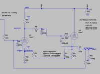
To linger on the #67 again: first #67 values (Vg1 is same as V006 node: the input summer)
View attachment 1054022
then my implementation:
View attachment 1054023
I have no scope pictures yet.
(I have to fix an earthing problem in one channel ...)
Well, of course the analysis you made to implement (and correct the phase issue you found out) starting from circuit # 67 is appreciable.
I then noticed you inserted some particular filters (I think for unwanted HF, possible oscillations...) but I don't know if they have been used just for the simulation.
I mean to say....in practice, in the real circuit what would be the essential changes to make without upsetting the boards (I would like to continue using the original pcb prototypes)?
Thanks for this. I've never seen that circuit before.
So, the feedback is implemented between the cathode of the input triode (the 12AX7) and the cathode of the SRPP's upper triode (6922)?
That would be the voltage divider formed by the 47k resistor between the cathodes and the pot labeled "GAIN 1".
Is that positive feedback? (I guess I could model it and find out...!)
How far from each other can the DC voltages at the cathode of the 12AX7 and the cathode of the upper 6922 be?
I figure the cathode of the upper 6922 is going to be at about 1/2 HT.
Does one need to be careful to make sure the cathode of the 12AX7 is also at 1/2 HT? Or can that be off by a bit? (And if so, how much off?)
Thanks for this. I've never seen that circuit before.
So, the feedback is implemented between the cathode of the input triode (the 12AX7) and the cathode of the SRPP's upper triode (6922)?
That would be the voltage divider formed by the 47k resistor between the cathodes and the pot labeled "GAIN 1".
Is that positive feedback? (I guess I could model it and find out...!)
OK, so I modeled it, I found out.
It is NFB. And...
Color me impressed!
That's an interesting and very well performing circuit. Thank you for sharing that.
I'm going to keep poking at it in simulation, see if I can understand how it's working.
A question:
I noticed that the 12AX7 has very little Ia, only about 500uA. The grid bias (Vk-a) is only 0.7V or thereabouts. There is likely to be some grid current happening in the 12AX7. Is that a problem? Or is the gm of 12AX7 so small that this is not a problem in actual practice?
Last edited:
I tried to modify the simulation circuit to have the PF in antiphase (in the light of the analysis above).
The results look good, I'm not sure if such a thing in the loop is feasible in the reality though...
By bypassing R3 (27k) you have basically unloaded your cathode follower for AC (audio) signal, raising the output impedance by a lot.
R9 and R5 now form the only AC load for the cathode follower, which is only 1.5k ohms. That's 1/10th the rp of the 12AU7, which means it's basically not loaded at all.
Did you apply a 1kHz sine wave of at least 100mV amplitude to see what the output looks like?
Try this directive for looking at sine waves:
Code:
.options plotwinsize=0
.tran 0 100m 60m 1u
.four 1k 10 v(out)
.OPTIONS numdgt=8
.option noopiterIt is my own original design. It is the workhorse amplifier for all my mixer designs. See: https://www.customtubeconsoles.com/Thanks for this. I've never seen that circuit before.
It is negative feedback. There are two things going on. The gain pot sets the closed loop gain, as you say, along with the 47K between the cathodes. Also, the gain pot is in parallel with the two resistors in the first triode's cathode circuit. It therefore also sets the gain of the first stage. The overall effect is that the the open loop gain largely tracks the closed loop gain. The result is the amount of negative feedback is very nearly constant which helps to ensure the circuit is unconditionally stable even though the gain can be varied from 6dB to 40dB.So, the feedback is implemented between the cathode of the input triode (the 12AX7) and the cathode of the SRPP's upper triode (6922)?
That would be the voltage divider formed by the 47k resistor between the cathodes and the pot labeled "GAIN 1".
Is that positive feedback? (I guess I could model it and find out...!)
How far from each other can the DC voltages at the cathode of the 12AX7 and the cathode of the upper 6922 be?
I figure the cathode of the upper 6922 is going to be at about 1/2 HT.
Does one need to be careful to make sure the cathode of the 12AX7 is also at 1/2 HT? Or can that be off by a bit? (And if so, how much off?)
There are two currents flowing in the 470R + 47K in the cathode circuit of the 12AX7. There is the 12AX7 cathode current plus the current through the 47K between cathodes. Hence there is always more current in the cathode circuit than in the 47K between if the 12AX7 cathode is at a dc voltage lower than half the HT voltage. To ensure there is a reasonable voltage across the 12AX7 and to allow a large enough value for its plate resistor, the design is arranged such that the cathode voltage of the 12AX7 is around 90V when used with a 300V supply.
Cheers
Ian
OK, so I modeled it, I found out.
It is NFB. And...
Color me impressed!
That's an interesting and very well performing circuit. Thank you for sharing that.
I'm going to keep poking at it in simulation, see if I can understand how it's working.
Thank you. It took me several years to come up with
Your HT voltage is a little on the low side. The design normally works with an HT of 300V although it is fine down to 250V. You should find this raises the 12AX7 current. Grid current is not a problem because of the negative feedback. The voltage between the grid and the cathode is equal to the input voltage divided by the loop gain due the the action of the NFB. Since this is typically 30dB it means the grid/cathode voltage is typically 1/30th of the input signal.A question:
I noticed that the 12AX7 has very little Ia, only about 500uA. The grid bias (Vk-a) is only 0.7V or thereabouts. There is likely to be some grid current happening in the 12AX7. Is that a problem? Or is the gm of 12AX7 so small that this is not a problem in actual practice?
Cheers
Ian
- Home
- Amplifiers
- Tubes / Valves
- A good route to a ECC82 preamp