Thanks.
It looks like you're in the older LTspice, version IV. Correct? If so, right click in the waveform window and select View > Spice Error Log.
A text window should pop up. Scroll down and it should display the total harmonic distortion for v(OUT). Do you see it? What does it say?
I noticed that the feedback voltage divider now has a 330k parallel resistor with a 27k series resistor. That should define 10X closed loop gain, but it looks like you have a 1V input signal and you're getting about 2V at v(out). That means you're getting more like 2X closed loop gain. What happens if you remove the NFB loop (disconnect the 330k resistor from the grid of V1)?
Also, the screen shot you uploaded is too out of focus to be able to read the printing on the schematic, so I may have gotten parts values and voltages wrong. I can hardly make them out on that schematic.
Now that is an interesting stage.

About the bypassing: the node Vcathode is floating, I need a capacitor to make a good sim without a DC shift . . . but better would be to use a connector and take that magic out of the schema.
About the AC load of the circuit #111-b: it is 1/(1/45+1/33+1/42k)= 13 K and the 12BH7 that I use as V3 can easily handle that load . . . but there is no real difference in output impedance with a standard ECC82 running some 6 mA.
The "filters" of .1p are non-existant. In fact they are there because of measured capacitances of the bare circuit board. (The RIAA board I use has 10pF capacitance because it has an earth shield layer on the board, great, but I wanted to know the impact. But it was very small in fact.Well, of course the analysis you made to implement (and correct the phase issue you found out) starting from circuit # 67 is appreciable.
I then noticed you inserted some particular filters (I think for unwanted HF, possible oscillations...) but I don't know if they have been used just for the simulation.
I mean to say....in practice, in the real circuit what would be the essential changes to make without upsetting the boards (I would like to continue using the original pcb prototypes)?
Thanks for the code, I can also use it! It is a very hard part to understand. And I am working on a Mac so that does not help (you're blind sort of), but it goes. The code is clean as ever!By bypassing R3 (27k) you have basically unloaded your cathode follower for AC (audio) signal, raising the output impedance by a lot.
R9 and R5 now form the only AC load for the cathode follower, which is only 1.5k ohms. That's 1/10th the rp of the 12AU7, which means it's basically not loaded at all.
About the bypassing: the node Vcathode is floating, I need a capacitor to make a good sim without a DC shift . . . but better would be to use a connector and take that magic out of the schema.
About the AC load of the circuit #111-b: it is 1/(1/45+1/33+1/42k)= 13 K and the 12BH7 that I use as V3 can easily handle that load . . . but there is no real difference in output impedance with a standard ECC82 running some 6 mA.
Now blimey. [An English phrase...] you have PFB in another phase than I did . . must be the lower NFB you have.Here it is
Thanks for the .asc. Now I can see that the capacitor in parallel with R3 is only 100pF. I thought it was 100uF! OK, what I wrote was wrong. V2 is still a cathode follower, just with a tiny value cap across it so it's no longer a cathode follower at very high frequencies. (Why?)
I'll upload the .asc as I've altered it, with the directives I use to analyze a modeled circuit (attached).
Here's what I found:
Open loop, the circuit only has 11x gain to begin with. With a 1kHz sine wave in set for 1Vrms out (1.414Vpk) I see 0.126% THD.
You've applied only about 6dB of NFB. That brings the gain down to about 5.7x. Closed loop, at 1Vrms out, I see 0.067% THD. (H2 is down -63.5dB)
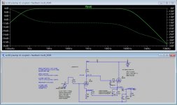
The frequency response is strange. It is only -0.5dB at 20kHz, but all those low pass filters you've installed accumulate to make a steep rolloff that's down -3dB at 41kHz. Why is that necessary? There's not enough NFB to risk instability...
Here's the closed loop frequency response using Ayumi N. 12AU7 models.

The CCDA circuit I offered up earlier, with positive feedback and a negative feedback loop, gave gain of 2.3X, THD of 0.025% with 1Vrms out, and -3dB at over 300kHz.

Also, bear in mind that the input impedance of the line amplifier is set by the NFB series resistor (R3 in the above circuit diagram). That means in your circuit, the input impedance is only 22k ohms. If a DAC or a CD player is the source, that's probably fine. But if you're using a 100k ohm pot as your volume control, its output impedance can rise to 25k ohms, which will load down completely into the 22k input impedance of the line amp. That's not good. That's why you see 100k ohms for R3 in the circuit above. An input impedance of 100k ohms shouldn't load anything down unduly.
I'll upload the .asc as I've altered it, with the directives I use to analyze a modeled circuit (attached).
Here's what I found:
Open loop, the circuit only has 11x gain to begin with. With a 1kHz sine wave in set for 1Vrms out (1.414Vpk) I see 0.126% THD.
You've applied only about 6dB of NFB. That brings the gain down to about 5.7x. Closed loop, at 1Vrms out, I see 0.067% THD. (H2 is down -63.5dB)
The frequency response is strange. It is only -0.5dB at 20kHz, but all those low pass filters you've installed accumulate to make a steep rolloff that's down -3dB at 41kHz. Why is that necessary? There's not enough NFB to risk instability...
Here's the closed loop frequency response using Ayumi N. 12AU7 models.
The CCDA circuit I offered up earlier, with positive feedback and a negative feedback loop, gave gain of 2.3X, THD of 0.025% with 1Vrms out, and -3dB at over 300kHz.
Also, bear in mind that the input impedance of the line amplifier is set by the NFB series resistor (R3 in the above circuit diagram). That means in your circuit, the input impedance is only 22k ohms. If a DAC or a CD player is the source, that's probably fine. But if you're using a 100k ohm pot as your volume control, its output impedance can rise to 25k ohms, which will load down completely into the 22k input impedance of the line amp. That's not good. That's why you see 100k ohms for R3 in the circuit above. An input impedance of 100k ohms shouldn't load anything down unduly.
Attachments
Last edited:
I relied on the frequency corrective changes from here:
https://audioxpress.com/article/you-can-diy-repurposing-an-old-preamp-for-line-level-duty
I only considered the second frequency pole (LP filter), in consideration of the fact that from the Ltspice graph the feedback loop bypassed led to a roll-off of -2dB before 20KHz, with those two resistor values.
By the way, when I ran the sim 'open loop' I meant with the positive feedback only. So the gain with positive feedback, but no negative feedback, was about 11x.
I experimented a bit with removing all those shunt capacitors and removing the positive feedback.
Removing the shunt capacitors raises the high frequency F3 from 41kHz to 530kHz. (12AU7 has very little Cag, so is good at high frequencies.)
Removing the positive feedback only lowers the gain by 0.5dB. Gain with the positive feedback is 15dB. Gain without the positive feedback is 14.55dB. I don't know if that's worth the bother.
I think I've proven to myself that the 12AU7 does run in most circuits with rather higher THD than other types, but it's not so bad you can't use it for some basic applications. A low-gain line stage with about 2x gain is one of those basic applications. You only need about 12dB of NFB to get there (open loop gain is about 18dB, minus 12dB and you have 6dB, or 2x voltage gain).
Just a few notes on my #111: I tested the bandwidth, is about 150 kHz, -3dB.
The sound is natural, violins have attack and remain clear, piano has body. I listened to a singer we went to a day ago (c branco) and she has that very dynamic voice, plus the Portugese gitarro that is so clear. It is just that little but of dynamics that add to the liveliness.
A Dutch famous audio engineer once lent me his NOS PCM1704 DAC that was very dynamic, exceptionally vibrant, with its PFB path. I’m not there but my preamp sounds relaxed in a way I like now.
I have a 50K pot in front. ALPS Black Beauty. At every volume setting the form of a square wave it the same. It might not be as lineair as it should be, but it is OK.
Have you by any chance removed the 220pF capacitor in g (V1)? I had mistakenly left it in the simulation circuit.
However, I have found that a lowering of R (in), leaving the other components unchanged, leads to an increase in the band at h.f. but it produces a noticeable peak between 0.5-1MHz.
Beyond C(byp) to the PFB to have the h.f. blunt I think a C(byp) of a few tens of pF at the NFB is also useful.
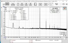
I ran a new test with REW, the distortion level of the last modified circuit is further improved (apart from the usual Noise due perhaps to the soundcard)
However, I have found that a lowering of R (in), leaving the other components unchanged, leads to an increase in the band at h.f. but it produces a noticeable peak between 0.5-1MHz.
Beyond C(byp) to the PFB to have the h.f. blunt I think a C(byp) of a few tens of pF at the NFB is also useful.
I ran a new test with REW, the distortion level of the last modified circuit is further improved (apart from the usual Noise due perhaps to the soundcard)
Attachments

Here is the sim file for #111. Real BW 150 kHz (sim says 108kHz), very low distortion. I use 12BH7 out and 5814 in.
And it can be used after a potmeter with no effects - the square wave = rise time of HF stays the same. Unlike many other preamps I made.
+ Very subtle highs, good lows. Nice voice. (no silly con sounds)
- My earthing problem (cross talk of the rising edge) might come because I have one earth line from the potmeter.
Attachments
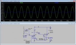
The 10 kHz square wave, at 9 V RMS:


I never had such a clear result with NFB across two tubes. I can imagine this is indeed a great topology for a mixer module.
Note no overshoot, just the typical slower dropping edge of cathode followers. [I had Wwhite Follower in mt RIAA. that of course was very symmetric.]
I never had such a clear result with NFB across two tubes. I can imagine this is indeed a great topology for a mixer module.
Note no overshoot, just the typical slower dropping edge of cathode followers. [I had Wwhite Follower in mt RIAA. that of course was very symmetric.]
Yes indeed this kind of result is great, perfect square waves at a high output for that circuit...
I went back to see better the # 111, I had not noticed the first inverting stage loaded at low current like a 12AX7 (no longer a ccda), and a quasi-constant Ik at the cathode in anti-phase (relating to feedback) with excellent waveform.
I went back to see better the # 111, I had not noticed the first inverting stage loaded at low current like a 12AX7 (no longer a ccda), and a quasi-constant Ik at the cathode in anti-phase (relating to feedback) with excellent waveform.
I redrew the 12AU7 linestage in your .asc into an LTspice sim of my own, ran it, and yes... It does look very good! I get (in the sim) 0.023% THD at 1V rms out, with nice wide bandwidth. I don't know how to generate square waves in LTspice (I've tried and failed), so I didn't do that. I just simulated with sine wave input.
I have a question, though... What is the purpose of the network R7 - R23 - C8 boxed in yellow, in the schematic?

Also, R11 looks like it's a build out resistor (cathode stopper) for the cathode follower. Why such a large value (430R)? Did you adjust that on test for best square waves?
100R is usually plenty, especially since you have C13-Ra installed too, which is a plate stopper. That's not usually used, and is not usually considered necessary. Did you find instability without C13 in place?
I have a question, though... What is the purpose of the network R7 - R23 - C8 boxed in yellow, in the schematic?
Also, R11 looks like it's a build out resistor (cathode stopper) for the cathode follower. Why such a large value (430R)? Did you adjust that on test for best square waves?
100R is usually plenty, especially since you have C13-Ra installed too, which is a plate stopper. That's not usually used, and is not usually considered necessary. Did you find instability without C13 in place?
Last edited:
Ha, the R7/C8 -R23 is for level shifting: in case a ECC83 is in position U2 then the anode is most often at 200 volt or above (the ECC83 needs to work in a high impedance to get best results).
I reused the circuit, so set R7 to one. That ism shorted. (in fact in the board I have 100 ohms as gate stopper). The ECC882 already has about 100V on the U2-anode and 110V on the output. No need for level shifting.
A square wave generatotor in spice: try it. (I didn't yet I just archived it )
PULSE(-1 1 0 100n 25m 50m)
I reused the circuit, so set R7 to one. That ism shorted. (in fact in the board I have 100 ohms as gate stopper). The ECC882 already has about 100V on the U2-anode and 110V on the output. No need for level shifting.
A square wave generatotor in spice: try it. (I didn't yet I just archived it )
** Blokgolf **
PULSE(0 5 0 1n 1n 50u 100u)PULSE(-1 1 0 100n 25m 50m)
Both measurements were made with no load, could I try a resitive load e.g. of 15k or higher? Sig. Ambrosini of Hifiaudio last time suggested me that a second step could be to test it with my amp connected, as real load.
Real world loads are going to be:
1. The shunt capacitance of any interconnect cable you use between your line preamp and the power amp(s)
2. Input capacitance of your power amp(s)
3. Input resistance of your power amp(s)
In LTspice, I put an Rload from output to ground to simulate power amp input resistance, and I put Ccable from output to ground to simulate cable capacitance and power amp input capacitance.
Try this:
Rload = 50k ohms
Ccable = 500pF (or 1000pF if you think your power amps might have particularly high input capacitance)
I also test with Rload = 10k ohms in case I think the line preamp might be used with one of these Class D amps that are so popular these days. I have a pair of powered speakers I like very much, and they have input impedance rated at 10k ohms. If I wanted to connect a line preamp to those speakers, I'd need 3 meter interconnects to each, so I also put Ccable = 1000pF as a torture test.
The above is why you'll see cathode stopper resistors and large value output coupling caps (4.7uF or higher) used in line preamps.
- Home
- Amplifiers
- Tubes / Valves
- A good route to a ECC82 preamp