Ok, I have to check how to tell to BBB to send i2s directly
What kind of Crystals do I need to replace stock one ?
Accusilicon are a good choice
Hello everybody !
I have checked how to connect the BBB to Ian's Fifo, the easiest way were to use a Raspberry but since I have a BBB, I will use it...
Do you think that I can use use small wires connected to GPIO socket or I soleder these wire directly to GPIO pins ?
Thank you !
Julien
I have checked how to connect the BBB to Ian's Fifo, the easiest way were to use a Raspberry but since I have a BBB, I will use it...
Do you think that I can use use small wires connected to GPIO socket or I soleder these wire directly to GPIO pins ?
Thank you !
Julien
I think normal wire (not too long though) is what most people use, it's what I use too at the moment. I used the shortest possible silver cable connection before but changed it to "longer" (~15cm) normal cable connection (not soldered), I think that works well too. It seems to be good practice to go as short as possible and when everything is in place in my DAC I will make me some of those coax cables as short as possible again and solder them on the DAC side similar to what Doede has in Post #7704.
But I don't think it's something essential as long as the cables are reasonable short.
Greetings
Oli
But I don't think it's something essential as long as the cables are reasonable short.
Greetings
Oli
Thanks Oli !
I will do like you suggested
What about the Master Clock ? There's no MCLK input on Ian's FIFOPI, so nothing to connect ? And from Ian's FIFOPI to DDDAC, I connect it ?
This is an I2S DAC, so there is "only" Data, L/R signal and Bit clock (BCK)
no master clock needed ! Even as it it is printed at the older motherboards at the input connector it is not connected to anything
")
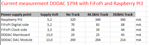
Measurement of supply currents
I am rebuilding my DAC in a new chassis so I have all boards on the bench and decided to finally do a proper supply current measurement.
Note: The clock side of the FiFoPi is with disabled on board LDO (short R58 and R59 points) and with the Accusilicon clocks
as questions on supply current always come back, I thought I should post the results here, FYI
Hope it self explaining
Attachments
Last edited:
I am rebuilding my DAC in a new chassis so I have all boards on the bench and decided to finally do a proper supply current measurement.
Note: The clock side of the FiFoPi is with disabled on board LDO (short R58 and R59 points) and with the Accusilicon clocks
Thank you for this Doede! I have a few questions.
1) When FiFoPi is paired with the WaveIO board do you still recommend feeding 3.3v to FiFoPi digital instead of 5v?
2) I bought a Vishay thick film 1/8 watt 0 ohm SMD resistor for FiFoPi LDO bypass (as instructed in the manual). But how difficult is this soldering effort? Everything is tiny. Did you use a resistor or just wire?
I am planing to purchase Wishay/Texas Zfoil resistor for my four deck DAC.
They are rated for 0.6W and will be (if I didn't mess) running at 0.22W.
I wonder if headroom is enough to have the resitors giving soundwise the best of what they can.
I am following up on this question, as I plan to do the same thing. Can 0.6W naked z-foil resistors work for I/V in a 4-DAC build?
Thank you for this Doede! I have a few questions.
1) When FiFoPi is paired with the WaveIO board do you still recommend feeding 3.3v to FiFoPi digital instead of 5v?
2) I bought a Vishay thick film 1/8 watt 0 ohm SMD resistor for FiFoPi LDO bypass (as instructed in the manual). But how difficult is this soldering effort? Everything is tiny. Did you use a resistor or just wire?
3) I am following up on this question, as I plan to do the same thing. Can 0.6W naked z-foil resistors work for I/V in a 4-DAC build?
sure no probs....
1) Waveio is indeed a special case, you know, may be I should try out all 4 combinations Waveio-isolated-output supply voltage versus FiFoPi-digitalside- supply-voltage.........… like 5-5 5-3.3 3.3-5 3.3-3.3 and report back what happens….
2) I just used a small wire bridge
3) 4-deck, Rload = 33 (or 34) Ohm - Bias DC = ~ 2,7 volt, hence power disipation is: 2,7 x 2,7 / 33 = 0,22 Watt - Verdict: yes you are good to go
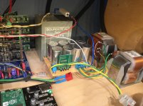
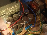
Doede, is the dac rebuild your isolation project?
Looking forward to see the pictures once done please!
yes it is. And pictures will come of course !
Due to Covid19, there is some delay for chassis delivery, so it will take at least a couple of weeks before this is ready (also Schaeffer must make the fron and back plates)
anyway…. good stuff takes time
It will have:
Arduino controlled (also volume TVC) with front panel input & IR remote control, LCD 4x20 read out
PI3 controlled LCD Display for music info (RoPieee) + RF remote control for streamer control
Being a Roon Bridge running under RoPieee
Input: PI3 (network and wifi), Waveio and SPDIF feeding FiFoPi through relais selector
Re clocking: FiFoPi with R58 / R59 bridged, supply 3.3V LDO - output using U/FL
Power supply1: Magic Power supply for DAC 4-deck and feeding clock section 3.3V LDO
Power supply2: SMPS 5V/4A, feeding both PI3's, Waveio USB power, Relais selector board and LCD display
Power supply3: 12 Volt LM317 module, feeding Arduino, DDDAC Home brew arduino TVC control board , Waveio isolated output and FiFoPi digital side via LDO (3.3 or 5V)
DAC: 4-Deck
Output: DDDAC Sowter TVC to XLR and cinch
Concerning the power Supply for the DDDAC, I don't know if Eduard is still there, but what value of caps do you use with 2 LL1694 ? Actually I have LL1691 -> 2200uF -> LL1694 -> 2200uF//100R//DDDAC. On PSUD2, I have a peak of about 14V at starting time, I don't know if it is or if I had to chang the value of caps to 4700uF for example ?
yes it is. And pictures will come of course !
Due to Covid19, there is some delay for chassis delivery, so it will take at least a couple of weeks before this is ready (also Schaeffer must make the fron and back plates)
anyway…. good stuff takes time
It will have:
Arduino controlled (also volume TVC) with front panel input & IR remote control, LCD 4x20 read out
PI3 controlled LCD Display for music info (RoPieee) + RF remote control for streamer control
Being a Roon Bridge running under RoPieee
Input: PI3 (network and wifi), Waveio and SPDIF feeding FiFoPi through relais selector
Re clocking: FiFoPi with R58 / R59 bridged, supply 3.3V LDO - output using U/FL
Power supply1: Magic Power supply for DAC 4-deck and feeding clock section 3.3V LDO
Power supply2: SMPS 5V/4A, feeding both PI3's, Waveio USB power, Relais selector board and LCD display
Power supply3: 12 Volt LM317 module, feeding Arduino, DDDAC Home brew arduino TVC control board , Waveio isolated output and FiFoPi digital side via LDO (3.3 or 5V)
DAC: 4-Deck
Output: DDDAC Sowter TVC to XLR and cinch
Excellent! Looking forward to see end results. Interesting sticking to 4 decks
…….. Interesting sticking to 4 decks
yes, as you can see, I normally do not go over the top. Nothing wrong with that, on the contrary … big fun for the hobby. But if you do, it need to be based on lots of experiments and listening. My free time is too limited for that, so I just enjoy what is working fine right now and what gives me musical joy. Even knowing it is always possible to get my own gear topped up a notch….
step by step in small steps so to say yes, as you can see, I normally do not go over the top. Nothing wrong with that, on the contrary … big fun for the hobby. But if you do, it need to be based on lots of experiments and listening. My free time is too limited for that, so I just enjoy what is working fine right now and what gives me musical joy. Even knowing it is always possible to get my own gear topped up a notch….
I sooooo agree! I have bought all the IAN stuff etc etc and still not had time to build it to my DAC
Still working as well but from home and more busy it seems with work
Ian FiFoPi digital side supply voltage
WaveIO with FiFoPi – logic levels issue
As promised, yesterday I checked the relations between Ian FiFoPi digital side supply voltage and the WaveIO Isolator Supply voltage (Which inherently drives the logic output level of the WaveIO of course)
I must admit something first - forget everything I wrote before on this topic (Supply voltages and WaveIO with FiFoPi) - I hate to admit it, but i made the common mistake myself, by just "making it work". See, you need to take time. But I was too eager to get the FiFoPi working with the WaveIO to do the comparison tests…. As it did not work immediately, I just fiddled around and by accident it worked and I did NOT check if the other changes I made (Like lower supply voltage for FiFoPi) were actually necessary!!
I should have read in more detail the FiFoPi manual (you always have to do this, but hey, I am human too: why RTFM?). It states clearly that all logic levels are LVTTL..... This level is based on a 3.3V Vdd.
Now it happens to be, that the interface between the 5 V CMOS and 3.3 V LVTTL parts have a lack of voltage tolerance; the LVTTL IC input is overdriven by the 5 V CMOS device output. And as the WaveIO has 5 Volt logic levels, this is exactly what happened…
Alright, enough ashes on my head
Here is the FINAL observation and guidance for a WaveIO to work nicely with the FiFoPi
1) The FiFoPi “5volt” supply voltage at J3 is not critical as there is a 3.3 Volt voltage regulation on the board. In my bench test setup the digital side of the FiFoPi worked well with supply voltage from 2.6V up to 5.5V (I did not dare to go beyond 5.5V…. So I am deciding right now to keep it on ~5Volt (which looks nicely conform) )
2) Adjusting the voltage at the WaveIO isolator from 2.6V (yes!) up to close to ~5V made no functional difference at all. BUT, getting the supply voltage just about over 5 volt and it stopped working correctly. Around the critical voltage point you get the typical digital crackle sounds and then after that is stops completely.
In conclusion what I will be doing to keep things simple (and that is my guidance as well) is the following:
FiFoPi: - J3 supply voltage 5 Volt
WaveIO: - Isolator supply voltage 3.3 Volt
The WaveIO isolator and FiFoPi digital (J3) can both accept 3.3v or 5v, right? So I still do not understand why your 5v power to J3 did not work initially. (SimonJ made a similar response in December to this curious problem.) Shouldn't any combination work, regardless of source?
Also, is there a reason you have now chosen to use 5v for J3 rather than its native 3.3v?
Also, is there a reason you have now chosen to use 5v for J3 rather than its native 3.3v?
Hi,
I made an upgrade on the ps on the dddac: the diode rectifiers are changed to a mosfet rectifier (no diode swich noise and lower voltage drop) and this made it possible to change to a choke input filter.
After a week running in, the sound with choke input and mosfet rectifier is a bit more relaxed and the high tones are more smooth.
@Doede: when you are at rebuilding your dac, why not change the rpi with a usbridge sig? This would be a very worthwile investment!
Attachments
- Home
- Source & Line
- Digital Line Level
- A NOS 192/24 DAC with the PCM1794 (and WaveIO USB input)