Ah, ok.
Would it not be more efficient to use 2 fifopo’s in order to keep the i2s lines as clean and short as possible?
Good point and question.
I really thought about this (I actually HAVE two FiFoPis with Accusilicon clocks) and this was my line of thought:
After the re clocking I want to keep things close and short and shielded - so the FiFoPi must be connected close to the DDDAC
I tested several sources (even not so good sources) and could not hear any (significant?) differences when I followed them with the FiFoPi connected directly to the DDDAC. For sure not the very audible differences when not re clocked or between non-re-clocked and re-clocked….
I wanted to have (my Dac is also used for testing around stuff) my DAC with both Ropieee streamer and USB Waveio input - So I needed a selector switch.
If I now do both with a FiFoPi, then I still would need a selector switch AFTER both FiFoPis going to the DDDAC... This seemed defeating the idea to keep things tidy and short after re clocking.
so after considering all of the above I decided to stick with selecting the source first, then re clock and stay short and close to the DDDAC....
Last edited:
Nice setup. I really like the floating shelves that match the racks
Thanks

A few more pictures of my build where I had the control knob custom made in a machine shop
Attachments
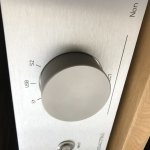
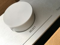
A few more pictures of my build where I had the control knob custom made in a machine shop
Nice build!
I like the choke ps. Is it choke input?
Good point and question.
I really thought about this (I actually HAVE two FiFoPis with Accusilicon clocks)
Good analysis. I would guess that it would be best to keep the leads from fifopi to dac as short as possible.
Groeten,
Nice build!
I like the choke ps. Is it choke input?
Thanks!
Yes choke input
Building another DDDAC currently which is on my second system and easier to alter etc
FiFoPi problem
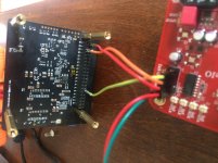
Can anyone think of why I can't get WaveIO and FiFoPi to work? I'm using:
5v --> WaveIO USB = recognized by the PC, appears to play fine
3.3v --> WaveIO isolator = good power confirmed by using a multimeter underneath the board on the V+/GND pins. FiFoPi's I2S LED lights up
3.3v --> FiFoPi digital = Empty buffer LED lights up
3.3v --> FiFoPi reclocker = Clock X01 LED lights up briefly, then switches to Clock X02
I'm using Accusilicon 45/49 clocks, installed in the correct orientation.
Everything seems to be in order but I am stuck on the Empty buffer; I cannot get FiFoPi to lock on.
Any idea what I'm missing?
Thank you!
Attachments
Can anyone think of why I can't get WaveIO and FiFoPi to work? I'm using:
5v --> WaveIO USB = recognized by the PC, appears to play fine
3.3v --> WaveIO isolator = good power confirmed by using a multimeter underneath the board on the V+/GND pins. FiFoPi's I2S LED lights up
3.3v --> FiFoPi digital = Empty buffer LED lights up
3.3v --> FiFoPi reclocker = Clock X01 LED lights up briefly, then switches to Clock X02
I'm using Accusilicon 45/49 clocks, installed in the correct orientation.
Everything seems to be in order but I am stuck on the Empty buffer; I cannot get FiFoPi to lock on.
Any idea what I'm missing?
Thank you!
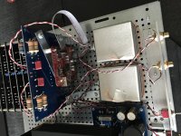
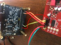
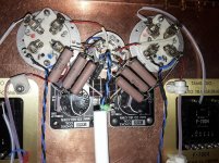
try adding an I2S signal-ground-wire to the FiFoPi…
I had similar. Routing the signal ground through the power ground seems to add problems.
PS: the red line is painted quite badly. it is not really pointing to GND of the pin header. GND are all 5 pins closest to the edge of the board...
Attachments
Last edited:
try adding an I2S signal-ground-wire to the FiFoPi…
I had similar. Routing the signal ground through the power ground seems to add problems.
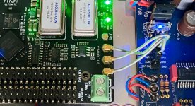
You are awesome. I added an I2S ground wire and got immediate signal lock. Thank you!!
You are awesome. I added an I2S ground wire and got immediate signal lock. Thank you!!
You're welcome of course - enjoy
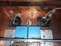
no need, you can do it like this (see below image)
may be…. in a future next design update I can add them of course… crossed my mind indeed.
Bought some of these really small coaxial connections cables to connect the IAN to the DDDAC and boy it will be micro surgery to separate the core from the coax braid
Attachments
Hello,
Now many people are forced to stay home there must be some volunteers willing to do time- and patience consuming tasks.
Most diy done by non experts like me take in fact to much time to finish. Because it is hobby time spend is not written down.
I am about to finish a long time project. Then another one is about to finish soon.
THEN i will start spending time on the DDDAC. Lots of developments going on just reading is already a task.
Greetings, Eduard
Attachments
Hello,
Now many people are forced to stay home there must be some volunteers willing to do time- and patience consuming tasks.
Most diy done by non experts like me take in fact to much time to finish. Because it is hobby time spend is not written down.
I am about to finish a long time project. Then another one is about to finish soon.
THEN i will start spending time on the DDDAC. Lots of developments going on just reading is already a task.
Greetings, Eduard
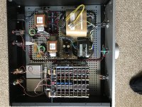
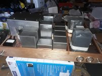
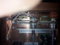
Very nice.
I see some very special Tamura transformers on the right

Are these the permalloy’s?
Hello Stefan Supersurfer,
Had them in the attic for 15 years or more. Bought in Japan in the good old days.
Greetings, Eduard.
P,s now line pre amp on the table ready to be finished in a few days. After a new chassis, a shunt supply with tubes ( Audiomagic) was added, now have to rewire one E80cc tube, AVC volume control, selector switch and some other stuff.
Attachments
Hello Stefan Supersurfer,
Had them in the attic for 15 years or more. Bought in Japan in the good old days.
Greetings, Eduard.
P,s now line pre amp on the table ready to be finished in a few days. After a new chassis, a shunt supply with tubes ( Audiomagic) was added, now have to rewire one E80cc tube, AVC volume control, selector switch and some other stuff.
Cool! With the Tango interstages
Now back on topic fast, before Doede wakes up
would these interstages be interesting as an i/v transformer on the dddac
Cool! With the Tango interstages
Now back on topic fast, before Doede wakes up
would these interstages be interesting as an i/v transformer on the dddac
Hello,
I already have the Sowters designed by Doede.
AND audiocreative developped another one too.
I will wait for the information to sink down before doing new investment.
Greetings, eduard
If you had a transformer that was designed for push pull operation and had a DC resistance near the required value for your DDDAC configuration, for instance 33 ohms for 4 boards, could you leave out the resistors and have just the transformer? If the transformer resistance was a bit above the ideal value you could use a resistor in parallel with the primary windings to get the correct DC load value.
I wonder if there are any standard transformers out there that would be candidates.
I wonder if there are any standard transformers out there that would be candidates.
If you had a transformer that was designed for push pull operation and had a DC resistance near the required value for your DDDAC configuration, for instance 33 ohms for 4 boards, could you leave out the resistors and have just the transformer? If the transformer resistance was a bit above the ideal value you could use a resistor in parallel with the primary windings to get the correct DC load value.
I wonder if there are any standard transformers out there that would be candidates.
The idea is technically valid of course. What would you expect to gain with this approach? installing a I/V resistor isn't such a big deal?
The transformer becomes the I/V converter. All of the dac’s current is then going in one path through the transformer. In the current setup we have the transformer shunting the resistor with dc and ac DAC currents flowing through both.
There are issue with this suggestion, probably many that I have not considered, but one that comes to mind is the output impedance of the dac “current source output”. I’m not sure about the 1794 chip, but in some cases these current sources do not have the ultra high Z out that the name would imply. If it is in the 2kohm range and you have 4 boards or 8 outputs parallel, the output Z would be 250ohms which would be in the range needed to drive a transformer directly. The matching of the transformer to this load is critical and perhaps not possible with off the shelf parts. It simply occurred to me that this approach would yield a more direct path for the DAC audio(AC) output current to get to the output of the transformer.
There are issue with this suggestion, probably many that I have not considered, but one that comes to mind is the output impedance of the dac “current source output”. I’m not sure about the 1794 chip, but in some cases these current sources do not have the ultra high Z out that the name would imply. If it is in the 2kohm range and you have 4 boards or 8 outputs parallel, the output Z would be 250ohms which would be in the range needed to drive a transformer directly. The matching of the transformer to this load is critical and perhaps not possible with off the shelf parts. It simply occurred to me that this approach would yield a more direct path for the DAC audio(AC) output current to get to the output of the transformer.
- Home
- Source & Line
- Digital Line Level
- A NOS 192/24 DAC with the PCM1794 (and WaveIO USB input)