As I said in my first post, I think if you want "punch", "kick", or "slam" used to describe the sound that the Karlson is capable of producing (this coming from someone who has only modeled the response of the K but has not yet actually heard one). And this is based on the very high sensitivity it can produce and throw out to a large distance from the 50 to 100 Hz region. If you have a large space like a massive listening room, a concert hall, an auditorium, a dance hall, etc. I think the Karlson will be very good given its wide dispersion capability and high sensitivity in the bass department.
From Freddi's comments about vocals, it sounds like it works very well there too. I need to find one and listen to it first hand.
From Freddi's comments about vocals, it sounds like it works very well there too. I need to find one and listen to it first hand.
X, this is all nice work that I've not seen anywhere else. First, thanks for putting it all out.
The 5m focus is interesting and seems quite fair given the applications. Never thought to do such a thing, personally.
This has all become a sort of one-stop reference so, here's an early rev from Moray James quite a while ago. It gets to the topic of increasing pathlength, or at least one of them.
This was obviously a smaller driver and maybe if he's around he can comment where it ended-up; it's just included as another way the creative minds have messed with things and just FYI.
Attachments
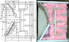
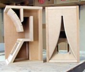
Hello Grindstone: those cabinets were designed for a Fostex FE166e. I still have them and they still sound very good. All my tapers are like a tractrix and the all stop at the top of the driver. The fiberglass damping shown turned out to be too much and most was removed to get the bass working. These speakers are able to stage and image extremely well. My later versions were all designed as K-Lines with the line entering the front chamber at the top front of the cabinet. In this way the taper section is included in the total 1/4 wave line length from the centre of the back of the magnet to the centre of the front of the cone.
Karlson's really are special and right now I am enjoying a set of one layer 2" id 5.6" long paper K-Tubes mounted on a pair of EV DH1A drivers. I may never buy another horn again. I run my k-tubes cross firing so the tubes are parallel to the floor and at ear level with the slots firing at each other so no radiation out toward the side walls. I could not be more impressed with the sound. Best regards and a big thanks for all the great simulation work in this thread, Moray James.
Karlson's really are special and right now I am enjoying a set of one layer 2" id 5.6" long paper K-Tubes mounted on a pair of EV DH1A drivers. I may never buy another horn again. I run my k-tubes cross firing so the tubes are parallel to the floor and at ear level with the slots firing at each other so no radiation out toward the side walls. I could not be more impressed with the sound. Best regards and a big thanks for all the great simulation work in this thread, Moray James.
Attachments
Last edited:
Moray James,
Awesome to hear that you are still enjoying your Karlsons. It's quite a strong statement to say you like the sound from a no cost 2 in dia paper tube more than any horn you can buy. If you can get me dimensions of your labyrinth boxes to model that would be appreciated.
Regards,
X
Awesome to hear that you are still enjoying your Karlsons. It's quite a strong statement to say you like the sound from a no cost 2 in dia paper tube more than any horn you can buy. If you can get me dimensions of your labyrinth boxes to model that would be appreciated.
Regards,
X
hello X - here's one by Greg B. to eventually model - his goal was to go lower than a regular K12 and hopefully have good response
http://img141.imageshack.us/img141/124/karlsonator.png
http://img141.imageshack.us/img141/124/karlsonator.png
Since it was brought up, here was an attempt to model it in MJK's old 'sections' sheet:

It's a bit of a kludge. Neither the effect of the K-slot nor the front stub loading is included, but IME this should still provide a reasonable expectation.
BTW, here is that flower horn concept. I actually meant them as midrange horns, around 300hz, so as to try it with my FE108E sigmas.

It's a bit of a kludge. Neither the effect of the K-slot nor the front stub loading is included, but IME this should still provide a reasonable expectation.
BTW, here is that flower horn concept. I actually meant them as midrange horns, around 300hz, so as to try it with my FE108E sigmas.
Greg,
Nice work on the MJK model, I see the prominent 'W' characteristic of all Karlsons. Did you ever make the Flower Power horn? I made a 4 panel square tractrix in foam core that I can easily cut some K slots into. That will be interesting to try with before and after measurements.
Nice work on the MJK model, I see the prominent 'W' characteristic of all Karlsons. Did you ever make the Flower Power horn? I made a 4 panel square tractrix in foam core that I can easily cut some K slots into. That will be interesting to try with before and after measurements.
hello X - here's one by Greg B. to eventually model - his goal was to go lower than a regular K12 and hopefully have good response
http://img141.imageshack.us/img141/124/karlsonator.png
Thanks for the link, I think this should be fairly easy to model as it is 2 dimensional. ( unlike Kenpeters' 3 dim folded K cabinet.)
re: "W" I think it can sometimes be minimal
look at KenL's coupler - there's a removable panel at the top. If that panel is removed and additional chamber added at that point, then things may change
response with W0838R and added chamber
my little 18" K with added 20l cap and a handful of polyfill - rear chamber is only 80 liters - it was pretty smooth without the added chamber. The extra chamber connects at the top of the front chamber
look at KenL's coupler - there's a removable panel at the top. If that panel is removed and additional chamber added at that point, then things may change
An externally hosted image should be here but it was not working when we last tested it.
An externally hosted image should be here but it was not working when we last tested it.
response with W0838R and added chamber
An externally hosted image should be here but it was not working when we last tested it.
my little 18" K with added 20l cap and a handful of polyfill - rear chamber is only 80 liters - it was pretty smooth without the added chamber. The extra chamber connects at the top of the front chamber
An externally hosted image should be here but it was not working when we last tested it.
An externally hosted image should be here but it was not working when we last tested it.
Last edited:
Moray James,
Awesome to hear that you are still enjoying your Karlsons. It's quite a strong statement to say you like the sound from a no cost 2 in dia paper tube more than any horn you can buy. If you can get me dimensions of your labyrinth boxes to model that would be appreciated.
Regards,
X
X: better than an horn that I have owned or heard so far. There are horns that I would love to hear but have not or have only had limited experience with at show.
Those little cabinets are long gone now and I cannot remember what I had in them. I built a fair number of small K-Lines for drivers I had on hand. Not all of them worked out as planed but were encouraging enough to prompt the next pair.
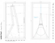
The two designs attached interest me most right now, however my shop access is limited these days do I would have to make a lot of plans and get my ducks in a row to build up either. Best regards Moray James.
Attachments
As far as I can tell there is no vent above the driver. The two designs are far more alike than different. The intent is to use a 1/4 wave line and to place the driver at a nodal point along the line. Perhaps Greg would comment they are his creations. Best regards Moray James.
the only vent in the Super t w a t is at the very top. When John Lapaire did some testing of the design, John made a rough testbox which at first had the Karlsonette vent - then converted to GB's scheme for comparisons. Imageshack loses a lot of my images so I don't have a really clear picture of the testbox front and will have to search for John's graphs. I do have a pair of similar height K-couplers with the Karlsonette position vent. Anyhow, Lapaire liked GB's scheme but the box was destroyed in a basement flood.
Lapaire's testbox which was loaded with FE206EN
Comparison of tuning of Karlsonette vent vs GB's tl-path in the same form factor
8" testbox, 6" testbox and Lapaire's K15
my HAK8 with Karlsonette type vent vs a factory 1960's K12
Lapaire's testbox which was loaded with FE206EN
An externally hosted image should be here but it was not working when we last tested it.
Comparison of tuning of Karlsonette vent vs GB's tl-path in the same form factor
An externally hosted image should be here but it was not working when we last tested it.
8" testbox, 6" testbox and Lapaire's K15
An externally hosted image should be here but it was not working when we last tested it.
my HAK8 with Karlsonette type vent vs a factory 1960's K12
An externally hosted image should be here but it was not working when we last tested it.
Last edited:
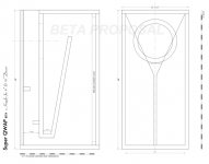
Model of Karlsonator with Kappa 12A
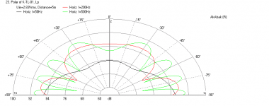
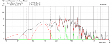
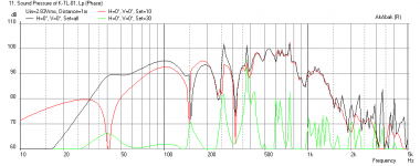
OK, I finished the model of the Karlsonator and it looks pretty interesting. It has much deeper bass extension but the punch falls off quickly as you move away from the speaker. Out at 5 m away the lower bass is kind of low and the remaining bass is in the 90 to 110 Hz range and at much lower SPL than the K15. So it is showing that the TL-terminated by K-slot is not as efficient as the K15 but has lower extension as shorter distances.
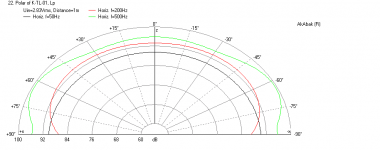
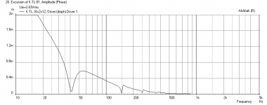
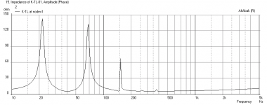
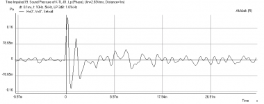
First plot is freq response at 1 m with 1 watt input, second plot is freq response at 5 m, third is the impedance, fourth is the speaker cone displacement, fifth is the polar dispersion at 1 m (good), and polar dispersion at 5 m (not so good), sixth plot is the impulse response at 1 m (good clean punch). So it is looking like the Karlsonator is good for smaller spaces where you want deeper bass extension. Cone motion is well controlled above 40 Hz, but it sort of gets out of hand if you have LF stuff from HT and such.
Does this response look anything like what folks have measured? I wasn't sure what driver to use so I picked the Kappa 12A.
hello X - here's one by Greg B. to eventually model - his goal was to go lower than a regular K12 and hopefully have good response
http://img141.imageshack.us/img141/124/karlsonator.png
OK, I finished the model of the Karlsonator and it looks pretty interesting. It has much deeper bass extension but the punch falls off quickly as you move away from the speaker. Out at 5 m away the lower bass is kind of low and the remaining bass is in the 90 to 110 Hz range and at much lower SPL than the K15. So it is showing that the TL-terminated by K-slot is not as efficient as the K15 but has lower extension as shorter distances.
First plot is freq response at 1 m with 1 watt input, second plot is freq response at 5 m, third is the impedance, fourth is the speaker cone displacement, fifth is the polar dispersion at 1 m (good), and polar dispersion at 5 m (not so good), sixth plot is the impulse response at 1 m (good clean punch). So it is looking like the Karlsonator is good for smaller spaces where you want deeper bass extension. Cone motion is well controlled above 40 Hz, but it sort of gets out of hand if you have LF stuff from HT and such.
Does this response look anything like what folks have measured? I wasn't sure what driver to use so I picked the Kappa 12A.
Attachments
-
 Karlsonator-Kappa12A-Polar-5m.png21.4 KB · Views: 86
 -
 Karlsonator-Kappa12A-Polar-1m.png20.7 KB · Views: 99
 -
 Karlsonator-Kappa12A-Displ.png24.1 KB · Views: 93
 -
 Karlsonator-Kappa12A-Impedance.png23.2 KB · Views: 161
 -
 Karlsonator-Kappa12A-Freq-5m.png29.2 KB · Views: 187
 -
 Karlsonator-Kappa12A-Freq-1m.png30.6 KB · Views: 197
 -
 Karlsonator-Kappa12A-Impulse-1m.png15.8 KB · Views: 92
So the burning question to me is what are the variables which contribute to shifting the impedance in a Karsonator or a Super T W A T? How about constricting the open line area? Clearly the longer line provides (as intended) greater bass extension so the missing element would then be a better impedance match to provide the great coupling of the K15. Your thoughts would be most welcome. A relatively compact (from a domestic point of view) design which work well in the near field would be the ticked for home use where most of us sit within the near field.
I have a suggestion. Can you model (on the Karlsonator version you just did) the eccect of a layre of camping in the line section which is placed on one wide surface? The damping would stay on the same surface following bends from start to finish. The intent he is primarily to develop consistent turbulence in the line and hopefully to increase the impedance of the line. Thank a million for this terrific opportunity to have you model like this, very much appreciated. Best regards Moray James.
I have a suggestion. Can you model (on the Karlsonator version you just did) the eccect of a layre of camping in the line section which is placed on one wide surface? The damping would stay on the same surface following bends from start to finish. The intent he is primarily to develop consistent turbulence in the line and hopefully to increase the impedance of the line. Thank a million for this terrific opportunity to have you model like this, very much appreciated. Best regards Moray James.
I cannot model damping in AkAbak. I am guessing that the throat CSA is important as well as the length of the line leading to the throat. The width and profile of the K slot on the front will probably be less of an effect. The volume of TL will be important as well as the location of the driver along the transmission line.
Last edited:
its a marvel to see believable simulations of the "Karlsonator" - - what can one do if they want good on-stage or outdoors punch in a K-coupler smaller than K15 which will reach some distance? My take with some music is that more punch with less effort will be perceived as better "bass" at some point than a less efficient system with lower cutoff that is working harder overall.
FWIW Carl treats K like a horn with first approximation of rear chamber volume around (qts*fs*vas)/50 - which could result in a very small back chamber for low qts. Does the Acoustic Control 115BK work just as well at a distance as Karlson's originals?
115BK internal layout side view. The ~27 sq.in. vent is centered in the upper board - internal width = 19 inches and the wings are radial arc with about a 1/4" starting gap
http://img490.imageshack.us/img490/9727/115bkside1sr4.jpg
Last edited:
- Home
- Loudspeakers
- Full Range
- A Speaker that Kicks Butt in Large Spaces