The coil, or the electro magnet jumping up and down around the permanent magnet (vibrating coil) creates tiny air waves, or sound waves, which the ear catches. Holding the coil tightly to the table gives out more sound and more bass. The waves on the table surface becomes longer, as the table top is too rigid. The paper disk glued to the coil makes louder sounds than the coil without it. The most important matter is that the disk vibrates differently radially. The same way, the cone of a standard speaker driver vibrates radially, somewhat hampered by the rubber surround and "spider."
The cone directs the sound, while the flat disk sends it everywhere. To get more low frequencies, the disk (or the cone) has to be boxed and dampened with a way for that back sound to slow down and escape -- longer it takes, slower it becomes - more bass.
By the way, a cone placed up side down on top of horizontally placed speaker box, above the driver would send the sound 360 degrees. Lot of speaker box manufacturers are selling this simple idea at exorbitant prices. Some of them place a sphere, instead of a cone.
Dome central area.
A few pic of the 10 1/2 inch square 1mmm panel with the central area made into a dome.
I got a bit carried away and coated the area around the dome with pva,which made the card bow outwards about at least an inch each side!!
I eventually managed to bend the card back but as you can see from the picture it's still a bit bent about a bit!
The bend ruined the mid to low frequency response.
I like the card sound ,I can see why paper cones have been around for over 100 years
I can see the card is going, probably ,to be my secondary smaller panel as I intend to be able to switch and even run together with my main set(EPS).I
The fr plot was with the previous thinner foil dome at about a metre or so.
I'm just testing different dome thicknesses.
Steve
Attachments


A few pic of the 10 1/2 inch square 1mmm panel with the central area made into a dome.
................
The bend ruined the mid to low frequency response.
I like the card sound ,I can see why paper cones have been around for over 100 years
I can see the card is going, probably ,to be my secondary smaller panel as I intend to be able to switch and even run together with my main set(EPS).I
The fr plot was with the previous thinner foil dome at about a metre or so.
I'm just testing different dome thicknesses.
Steve
Nice testing!
What would happen, if you put the "exciter" on the other side of the card, so the card would have slightly concave outwards? By the way, what is the sound coming from the back side? Would that side give you better mid to low sound?
If you have time, have a look at this video. The guy is assembling a driver. It is Hindi, I don't understand it too, but the video tells a story. The cone is wavy, which tells us that vibrating surface of the cone gives out sound. Actually, DMLs prove it.
Also, to create a DML, all you need is the permanent magnet, yoke and the coil, one can glue the panel, just above the spider. There should be a very short chassis to suport the panel. Between the chassis and the panel, rubber tube could be placed to separate the two. It might be cheaper than buying an "exciter."
Last edited:
SteveA few pic of the 10 1/2 inch square 1mmm panel with the central area made into a dome.
I got a bit carried away and coated the area around the dome with pva,which made the card bow outwards about at least an inch each side!!
I eventually managed to bend the card back but as you can see from the picture it's still a bit bent about a bit!
The bend ruined the mid to low frequency response.
I like the card sound ,I can see why paper cones have been around for over 100 years
I can see the card is going, probably ,to be my secondary smaller panel as I intend to be able to switch and even run together with my main set(EPS).I
The fr plot was with the previous thinner foil dome at about a metre or so.
I'm just testing different dome thicknesses.
Steve
Thank you a lot for sharing your experience.
Water based glue always altered natural fibre ime and I‘ve thought to apply instead fast drying alcohol based glue and/or to control the drying process with heat and pressure. A good and easy method for this is still on my want list. Btw, in my experiments I try to use as little as possible plastic based material and if possible I avoid animal based glue as well, unfortunately. Some very good recipes of glue are with skin or bones. Probably an exception is required here ...
Eric
Last edited:
Eric.
When I glued the two .5mm card panels together with pva to produce a 1mm panel I sandwiched it between two pieces of ply until dry,this gave a pretty flat panel.
I did wonder if the stretching technique for paper might work on card?
But I think I'll have to find a coating that prevents bending with time and moisture ,which hopefully sounds as good.
When I coated one side of a largish 5mm xps panel with pva,it bent horribly,but coating the other side pulled it back into place.
If I'd sealed and coated the panel to start with it would have saved a lot of pain,but at the time i didn't know how far I was going to go with this panel.
The other older 0.5mm card panel I'm using with the same dome at the moment,is one I first coated in pva ,then vinyl silk ,it could probably just as well have been gloss paint?
I use pva first as it's a glue and tends to soak into the panel for a firm exciter mounting,vinyl will will tend to pull away with time,so I paint around the exciter area.
Steve
Attachments


I did wonder if the stretching technique for paper might work on card?
Steve
Bristol paper is a typical British product, available at any stationary shop. Once wet-dry it is very stiff. Once dry, you can take the timber frame off. It'd keep the bent edges at 90 degrees.
Wikipedia.
Last edited:
DML subwoofer anyone?
After reading about the post about Bristol paper I decided to try something...
I have a roll of brown painting dust cover paper ( the brown paper on the back of paintings ) like Bristol paper once you've attached it to the canvas you wet it to stretch it tight. The sound I got was not at all what I expected, Very VERY good response from about 35 to 200ish hertz above that is pretty much non existent. Panel was a basic wood frame (450mmx600mm) with paper stuck on the front with contact adhesive, first tried with plain water and then pva/water mixture with no real benefits. I do think this can be used as a low frequency driver with a smaller eps/xps panel to pick up the highs.
Interesting!
Brown paper has a different consistency and texture. Maybe, you should have a look in the stationary shops to find something like Bristol paper. They are usually sold in A2 size. You might even find some paper thicker than that. Bristol paper is more like a card.
Thanks for the info jmatt.
How did you mount the exciter to the paper,did you use a frame to support the exciter?
I must admit I would have expected some hf from the central area of the exciter,at least.
This is a cheap and easy panel to test ,so will probably give it a go.
Steve
How did you mount the exciter to the paper,did you use a frame to support the exciter?
I must admit I would have expected some hf from the central area of the exciter,at least.
This is a cheap and easy panel to test ,so will probably give it a go.
Steve
I have a feeling that you don't need large paper (wet - dry) to get good sound out of the panel+exciter. It could be small, for example A6 (148mm x 105mm). The corners should be curve cut. If Bristol paper is not available, you can paste 3-4 normal printer papers together with starch, and once dry do a wet-dry stretching. Try the A4 size first, but later cut to A6 size and see.
Thanks for the info jmatt.
How did you mount the exciter to the paper,did you use a frame to support the exciter?
I must admit I would have expected some hf from the central area of the exciter,at least.
This is a cheap and easy panel to test ,so will probably give it a go.
Steve
I mounted the exciter to a 100mm balsa disk and then to the paper, also used a wooden spine to support the driver.
JMatt.
I'm a little more confused now?
A 2mm 100mm balsa panel on its own should have a fairly good response from about 600hz to 20k if my memory serves me well.
I can't fathom why attaching paper would stop this?
It works with the canvas art frame panel 40hz to 20k?
Any chance of a picture or a fr plot?
Thanks .
Steve.
Attachments

Hi all,
New here. In the process of trying to ingest this massive thread, and I started in the middle, thanks to a Google search landing me there. I apologize if these questions/concepts have been addressed in the pages I haven't read yet but I feel compelled to ask after reading veleric's post 1407.
It seems like a lot of the posts seem very focused on achieving a balanced frequency response on a single panel. That's all well and good but essentially all good full range speakers, at least in the traditional cone driver/cabinet sense, are usually 2 way drivers. I know the TI video which sucked most of us into this world even used 2 speakers per channel, of differing substrates, to try to balance out, or extend the range. Even in this case the two panels were both rectangular, and were running full-range, and presumably in phase, minus the fact that there was some compensation from one driver on each side being center-mounted, while the opposed was 2/5,3/5. Veleric's breakdown in the reference post touched on shape, specifically parallels, the problems with "natural tones" and the fact that the more frequencies you spread simultaneously over a panel, the more cross-conflict and cancelation you will get, and how overall size plays well to some frequencies and less to others. These things get touched on in the Tall Blonde discussions and those about damping.
So my question/proposal is 2 fold, with some tangents.
1. Yes, a relatively level response from a single panel is a respectable goal but for the final product why aren't we taking more of a 2-way approach, using 2 panels per channel _and_ a crossover network? It seems to me that this would not only reduce frequency clashes/cancelation across the spectrum, it would allow for the flexibility to damp panels independently for best effect. This would be helpful regardless of if you did or didn't want to use different substrates.
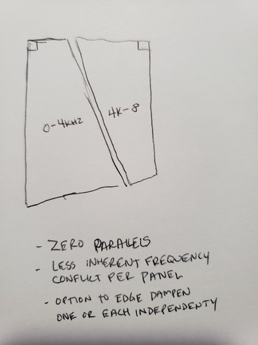
2. Why isn't there more conversation/analysis about the effects of shape besides rounding corners, etc.? I know that our sense of asthetic, and western society's obsession with right angles, makes our eye twitch when we see shapes without opposing parallels. But what if we employed more eccentric shapes, just not so extreme as to drastically compromise surface area. See my attached crude drawing. There are no parallels, which could possibly/theoretically help with panel and room response, if I'm not mistaken.
Tangent 1: When dealing with natural substrates like wood, I would think that grain would come into play, even in layered ply. You are going to have more total long grain running in one direction than the other as long as your panels are not square. This touches back to the Tall Blonde speaker discussion. I would think that length and direction of grain would have an effect on resonances. Has anyone done FR testing on 2 oblong panels of the same material with the grain running along the long side vs short side to see how/if it differs?
Tangent 2: Regarding room response, I have seen a little discussion about closed backs on frames and other things and lots about the bi/di/chaotic pattern effects of these panels. Also, in the YouTube video where the guy made the ridiculously tall panels for his log cabin, he references a rule I haven't seen mentioned elsewhere about the distance from the wall being calculated by the size of the panel. How does that come into play? And more related to the fact that I am interested in suspended applications vs floor, has there been much discussion/testing of using sound absorbing materials on the wall behind a hanging panel to change the way the rear waves reflect? Would reducing or damping those possibly have positive effects on room response?
Thanks for indulging my long-winded Adhd-fueled curiosities. Don't be afraid to tell me to keep reading this thread
 if these horses have already been beaten to death.
New here. In the process of trying to ingest this massive thread, and I started in the middle, thanks to a Google search landing me there. I apologize if these questions/concepts have been addressed in the pages I haven't read yet but I feel compelled to ask after reading veleric's post 1407.
It seems like a lot of the posts seem very focused on achieving a balanced frequency response on a single panel. That's all well and good but essentially all good full range speakers, at least in the traditional cone driver/cabinet sense, are usually 2 way drivers. I know the TI video which sucked most of us into this world even used 2 speakers per channel, of differing substrates, to try to balance out, or extend the range. Even in this case the two panels were both rectangular, and were running full-range, and presumably in phase, minus the fact that there was some compensation from one driver on each side being center-mounted, while the opposed was 2/5,3/5. Veleric's breakdown in the reference post touched on shape, specifically parallels, the problems with "natural tones" and the fact that the more frequencies you spread simultaneously over a panel, the more cross-conflict and cancelation you will get, and how overall size plays well to some frequencies and less to others. These things get touched on in the Tall Blonde discussions and those about damping.
So my question/proposal is 2 fold, with some tangents.
1. Yes, a relatively level response from a single panel is a respectable goal but for the final product why aren't we taking more of a 2-way approach, using 2 panels per channel _and_ a crossover network? It seems to me that this would not only reduce frequency clashes/cancelation across the spectrum, it would allow for the flexibility to damp panels independently for best effect. This would be helpful regardless of if you did or didn't want to use different substrates.
2. Why isn't there more conversation/analysis about the effects of shape besides rounding corners, etc.? I know that our sense of asthetic, and western society's obsession with right angles, makes our eye twitch when we see shapes without opposing parallels. But what if we employed more eccentric shapes, just not so extreme as to drastically compromise surface area. See my attached crude drawing. There are no parallels, which could possibly/theoretically help with panel and room response, if I'm not mistaken.
Tangent 1: When dealing with natural substrates like wood, I would think that grain would come into play, even in layered ply. You are going to have more total long grain running in one direction than the other as long as your panels are not square. This touches back to the Tall Blonde speaker discussion. I would think that length and direction of grain would have an effect on resonances. Has anyone done FR testing on 2 oblong panels of the same material with the grain running along the long side vs short side to see how/if it differs?
Tangent 2: Regarding room response, I have seen a little discussion about closed backs on frames and other things and lots about the bi/di/chaotic pattern effects of these panels. Also, in the YouTube video where the guy made the ridiculously tall panels for his log cabin, he references a rule I haven't seen mentioned elsewhere about the distance from the wall being calculated by the size of the panel. How does that come into play? And more related to the fact that I am interested in suspended applications vs floor, has there been much discussion/testing of using sound absorbing materials on the wall behind a hanging panel to change the way the rear waves reflect? Would reducing or damping those possibly have positive effects on room response?
Thanks for indulging my long-winded Adhd-fueled curiosities. Don't be afraid to tell me to keep reading this thread
This picture shows some of my various shaped panels over the last 10years.
As for how many exciter or panels ,that is up to you,you can make it as complicated as you like,multiple amps,eq,xo,you name it.
All the things you have mentioned have been discussed on various threads on the web over the years.
It's a long read ,you'll be grey haired like me by the time you've finished reading them all,plus patents .
When I first started looking into dml,I purchased 40 or so exciters ,as it was thought that like the podiums ,the more the better!
That is why I have so many panels lying around with exciters still attached.
I have found dml interesting and fun.
Hope you will too.
Steve
Attachments

Last edited:
Of course as soon as I post this I hit a chunk of threads about arrays and eccentric shapes. LOL.
But what if we employed more eccentric shapes, just not so extreme as to drastically compromise surface area. See my attached crude drawing. ...
Interesting line of thought.
As sound waves move away from the source radially, why not use disks? Even in a cone, the waves move along the cone surface and on it, radially. So, why not use two different materials for the panel, one for mid/low, one for high?
Thinking about the sound waves coming out of the back, and to get lows out of it, why not box the back and leave a bass-reflex hole (or a transmission line) out of that?
Attached is a two material drawing of a disk.
Attachments

I did find a patent that I used as a reference for different shapes of panel,which was helpful,but I'm afraid my wife deleted it from the computer!
I have tried to find it again without success,it must have been by chance that I found it in the first place.
Like ordinary speakers very large very small complicated or simple,they all have their followers,which is best depends on which is best for you.
I am always up for trying new ideas as long as it doesn't break the Bank.
I even try ideas that I think can't work ,just in case? That is As long as it isn't too expensive.
The other day I tried to measure my dome on an exciter unit ,but the exciter itself was making so much noise ,I could not get a decent fr plot.
This is one of the reasons I keep looking at the more powerful piezoelectric units that are going around,the only reason I haven't made the jump yet is that I'll have to fork out on piezo amps as well!
It should all cost below about £100 to test,if it fails then it's money down the drain.
Although I'm sure they could still be used as a mid tweeter dml for the panels that have hf problems.
Oh no I'm still trying to talk myself into it.
I'm not going to be able to buy much now the lock down has started again but there are a few things I can knock together and try,if only to stop the boredom.
Steve
Might be better with the inner disk surrounded by triangular shapes, so it looks like a fat multipointed star. I'd then expect a softer transition between the two materials with respect to the two strong resonant modes these coaxial disks would have.
Chdsl.
You seem to be describing a BMR ?
Steve
The people, who try to earn money out of this explain,
"Balanced Mode Radiators (BMRs) combine bending wave mode technology with pistonic motion to create full audio range, wide directivity speaker drivers for lifelike sound reproduction."
And, also,
"The BMR is a flat-diaphragm driver that features greatly reduced breakup and extremely broad dispersion..."
After all, the DML is trying to do the same thing.
The "high-end" BMR manufacturers are using extremely thin diaphragm disk surrounded and fixed by the same way as the normal cone. Sony tried this with their APM series, and dropped it quite sometime ago.
Attachments

Last edited:
- Home
- Loudspeakers
- Full Range
- A Study of DMLs as a Full Range Speaker