Christian,Thank you Eric for the link. It is a very good source.
In the "Plate" section they give the formula of the Eigenfrequencies for a free edge plate.
Do you think the edge conditions of our panels are close enough of the free conditions?
Actually, what they give in that link are not the equations for free edges, but rather for "simply supported" edges. "Simply supported" means the edges can't move, but can freely rotate. I may be wrong, but I don't think their are similar simple equations for the eigenfrequencies of plates with free edges. I think there are only numerical solutions. I think there may be equations for clamped edges, but I'm not sure about that.
I do think that plates hung from strings are pretty nearly free edge plates, although the placement of the strings does have an influence. The place with the least influence would probably be about 10% to 20% of the panels length from the ends.
I have always assumed that a panel attached to a frame using foam around the perimeter of the panel would act substantially as a "simply supported" plate. But I'm sure the thickness and softness of the foam, and stiffness of the frame will influence whether or not such a panel actually behaves like a theoretical simply supported plate. This is something I'm currently investigating.
For the calculation of the natural frequencies (eigenfrequencies) of panels, I use finite element modelling software called LISA.
https://lisafea.com/
LISA is pretty easy to learn, and allows simulation of free, simply supported, or clamped edges. It also allows for orthotropic materials (different stiffness in different directions) like plywood. The free version is limited to 1300 nodes, but that should be enough to model most any panel. I paid for the full version (for other applications), but my panel model uses only 1600 nodes, and I suspect a 1300 node model would work just as well. If you are really interested in being able to predict/understand mode shapes and frequencies, it's an awesome tool. As a specific example, I recently realized it's pretty easy to use LISA, combined with some simple RTA analysis in REW to determine the elastic moduli (and hence D) of panels with much better accuracy than the simple bending tests that you and I discussed earlier.
Eric
If I follow you analysis... for example among the first modes shown, only the number 1 and 4 give a pressure at distance? Meaning that many modes are useless?
Christian,
Yes, basically, at least at low frequencies. It's perhaps an over simplification to say the other modes are useless, but they are much less efficient, especially at low frequency.
See the figure below from this paper:
https://www.researchgate.net/public...nt_Forces_Using_its_Surface_Resistance_Matrix
All modes radiate sound equally well above the coincidence frequency, but at low frequency the odd/odd modes radiate much better. The modes 1 and 4 from the previous link are the (1,1) and (1,3) modes in this paper.
Disclaimer: I have not yet read this particular paper, but I have seen similar figures in other papers. It looks like it might be an interesting one.
Eric
Attachments
https://www.audiocircle.com/index.php?action=gallery;area=browse;album=19454
To save me from having to measure a ply free floating panel again ,I thought I'd show this link.
With my exciter I had a good frequency response at 1m from about 30hz to 20k.
And also with ply and my exciter I always found the tell tale hump from 10k to 20k.
When I measured from the side as in the right picture the HF holds up well , even down to the mid hundred hz.
I never really new how much was reflecting from the walls in my room , so I was hoping that you might be able to measure from the sides to confirm or not the ply response from the side ?
If I remember correctly the hf on my ply panels spread to the edges of the panel without loss ?
You can click on the pictures to enlarge them.
In the end I rigidly screwed the ply panel to something like a 2inch by 3inch frame which gave me a higher output, that better matched my 10watt exciter.
I recommend this for pro use with a more robust exciter.
Steve.
Thank you for the feedback about "free edges" and "simply supported" Eric.Christian,
Actually, what they give in that link are not the equations for free edges, but rather for "simply supported" edges. "Simply supported" means the edges can't move, but can freely rotate.
...
For the calculation of the natural frequencies (eigenfrequencies) of panels, I use finite element modelling software called LISA.
...As a specific example, I recently realized it's pretty easy to use LISA, combined with some simple RTA analysis in REW to determine the elastic moduli (and hence D) of panels with much better accuracy than the simple bending tests that you and I discussed earlier.
I just downloaded Lisa and I will have look if it is usable under linux with Wine to emulate Windows (I would prefer not to reopen Windows cession) and what I understand.
A combination of REW and LISA seems promising. Let us informed of your progress.
Christian
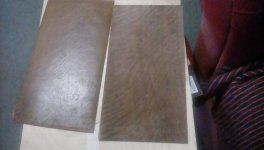
I just remembered that a couple of weeks ago I found two pieces of old .5 mm veneer in my shed ,which had peeled off of some old draws.
they were very wrinkled but I soaked them and placed them in between two ply boards.
they look pretty good now.
I have a choice of making one 1mm panel 34cm by 17cm or two panels 17cm by 17 cm maybe with a little off set on one side so it is not square ?
Should be interesting.
When I get around to it that is.
Steve.
Attachments
Before sharing some results from "basic" tests I would like to say that canvas panel in addition of being a very good full range is very useful to support tests. By its size, it is more easy to go for a short test without having to push furniture. I think it is perhaps the best choice to start with panels : few components, almost standard. Really a good choice.
So in the attached document some results of basic tests I set up to check characteristics of DML or some ideas. As for other tests, some results are expected (even if not understanding the exact reason), some not.
Christian
So in the attached document some results of basic tests I set up to check characteristics of DML or some ideas. As for other tests, some results are expected (even if not understanding the exact reason), some not.
- baffle : not so much effect. For sure not as expected on the peaks in the medium
- rounded edges : same effect as the baffle with a smaller dimension (nice look compare to the baffle!). The canvas with the rounded edges are now playing. Pleasant; No big trouble I think (even if is not really a listen test). The sensation of the plywood panel is still missing.
- Directivity : confirmed very very low. even if known it is always incredible to see; so low changes between 0 and 60°
- Effect of additional mass at the voice coil : here also the effect is very low. No low pass filter appears even when the voice coil mass is multiplied by 5!. More difficult to understand.
Christian
Attachments
Hi Steve...so I was hoping that you might be able to measure from the sides to confirm or not the ply response from the side ?
If I remember correctly the hf on my ply panels spread to the edges of the panel without loss ?
The exchanges are dense... not sure to understand what you want neither what previous question you are referring... sorry.
A measurement is I think possible. What would you like, the microphone aiming at the panel edge (like a 90° test)? What distance ? I don't know if my panels are the right candidates because they have a frame for the suspension and a piece of wood covering each side (see the edge on the picture)
If you remember, I posted some times ago how I tried to measure the wave speed in the membrane. I am trying to improve the script to get information from the record... It seems that the attenuation of the wave going through the membrane decreases suddenly above some kHz. Not fully sure but seems. It goes in the same way that what you see and want to check.
Christian
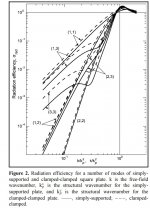
Ouch! far in advance to my knowledge but yes seems one of the missing link between membrane movements and distant pressure. And yes all the modes seem not having the same level.Christian,
Yes, basically, at least at low frequencies. It's perhaps an over simplification to say the other modes are useless, but they are much less efficient, especially at low frequency.
See the figure below from this paper:
https://www.researchgate.net/public...nt_Forces_Using_its_Surface_Resistance_Matrix
All modes radiate sound equally well above the coincidence frequency, but at low frequency the odd/odd modes radiate much better. The modes 1 and 4 from the previous link are the (1,1) and (1,3) modes in this paper.
Disclaimer: I have not yet read this particular paper, but I have seen similar figures in other papers. It looks like it might be an interesting one.
Eric
I found yesterday (or is it a link in a post before...) the same concept of radiation efficiency in this paper a kind of introduction to DML If you have the key to explain figure 2 (similar to the one in your link), welcome
Last edited:
@VelericThank you for the feedback about "free edges" and "simply supported" Eric.
I just downloaded Lisa and I will have look if it is usable under linux with Wine to emulate Windows (I would prefer not to reopen Windows cession) and what I understand.
A combination of REW and LISA seems promising. Let us informed of your progress.
Christian
LISA seems Linux friendly with the Wine emulator. Great. Would it be possible you share a simple file or advice for a tutorial? I am a bit like a chicken in front of a knife!
....
Forget it for now... I got an error while running the beginner example!!!! The emulation seems not work so well.
Christian
Last edited:
I have been thinking about the high frequency drop off of my DMLs.... 2 questions:
1 - has anyone measured the impedance curve of a DML speaker?
2 - does voice coil inductance hurt high frequency efficiency?
I don't have the impedance curve of my exciters but I have looked at those of a few and they all have rising impedance and falling output at higher frequencies. I have similarly crazy high frequency boosts on my current DMLs and they sound great. So I am guessing the rising impedance attenuates the power amplification. It still sucks because I will probably lose 5-6dB of output across the rest of the spectrum for balance but I have watts to play with. This is yet another consequence of asking one voice coil to cover ~8 octaves I guess.
Christian.
Did you look at my link in my post 4383 ?
I measured from the front at 1m and then from the side at 1m.
I took the exciter as the 1m point in both cases.
You can take the measurement 1m from the side of the panel if you wish, it's just to see what the response is from the side without any wall reflections.
I couldn't load your attachments on page 4386 to my kindle so will try again tomorrow on the computer.
The canvas panel can be improved cheaply ,I'm sure.
When I first heard the canvas panel ,and I was using only the one, I had to check that the TLS were turned off as I could not believe the low frequency output I was hearing !!
On NXT RUBBISH we were building bigger and bigger panels to increase the low end performance.
Who would have thought a small canvas panel could do a better job .
My veneer panel is pretty good too ,I'm happy to say.
Steve.
1 - not yet from my side. This test was not for me a "priority" so far in a first approach I don't really care above 10k until it has no crazy annoying level (was the case with XPS). Nevertheless, it is on my "dolist" more to see the resonance peaks due to membrane material.I have been thinking about the high frequency drop off of my DMLs.... 2 questions:
1 - has anyone measured the impedance curve of a DML speaker?
2 - does voice coil inductance hurt high frequency efficiency?
I don't have the impedance curve of my exciters but I have looked at those of a few and they all have rising impedance and falling output at higher frequencies. I have similarly crazy high frequency boosts on my current DMLs and they sound great. So I am guessing the rising impedance attenuates the power amplification. It still sucks because I will probably lose 5-6dB of output across the rest of the spectrum for balance but I have watts to play with. This is yet another consequence of asking one voice coil to cover ~8 octaves I guess.
2 - I think there is no reason not having a low pass filter between this voice coil inductance and the voice coil resistance (so less current so less force so less pressure). DAEX25FHE4 is given for Le = 0.1mH (at 1kHz) and Re = 4.3Ohm. fc = Re / (2pi.Le) = 6400Hz. Because of magnetic loss, Le is probably a little bit higher. In the doubt of the effect of voice coil mass, voice inductance; having both low was a reason of my choice of this exciter (low mass, low inductance, quite high force factor, not too low power capacity). What about yours?
All the impedance curves are rising : yes as any electrodynamic motor.
All with falling output : most I think and in different quantity. Spedge panels are counter-example (could question why?). As Spedge mentioned, the 10k-20k range is probably another area with so short wavelength that other mechanico-acoustic phenomena occur. In this range we can suspect the wavelength being some centimeters so the voice coil diameter (other reason of my exciter choice : a 25mm diameter not a 32mm... this is just opinion/feeling not well constructed design rules).
In addition, the effect of a serial inductance is "slow", 6dB per octave. The change in the FR if I remember previous curves are faster.
In words of octave, yes the the requirement is high. As mentioned if DML introduction papers something like 8 octaves with alow directivity, far from the performance of any cone speaker. It seems reasonable to target the useful range 300 to 20k which is 6 octaves (correct?) which leads to a first resonance frequency target for the panel at about 70-80Hz so yes 8 octaves. Nice device no?
Christian
Steve, yes I had a look to the link seeing the the rising 90° FR. I understand you have an interest for an outdoor measurement.Christian.
Did you look at my link in my post 4383 ?
I measured from the front at 1m and then from the side at 1m.
I took the exciter as the 1m point in both cases.
You can take the measurement 1m from the side of the panel if you wish, it's just to see what the response is from the side without any wall reflections.
I couldn't load your attachments on page 4386 to my kindle so will try again tomorrow on the computer.
The canvas panel can be improved cheaply ,I'm sure.
When I first heard the canvas panel ,and I was using only the one, I had to check that the TLS were turned off as I could not believe the low frequency output I was hearing !!
On NXT RUBBISH we were building bigger and bigger panels to increase the low end performance.
Who would have thought a small canvas panel could do a better job .
My veneer panel is pretty good too ,I'm happy to say.
Steve.
The outdoor measurements I shown where done last summer in our secondary house. I will see what it is possible. It is winter now and the garden of our main house is smaller!
for the size, for the simplicity, the canvas are for sure incredible. I had to build them to be convinced they can go low. We are so in the paradigm of a link between the dimensions and the lowest frequency.
Despite that, they still have something missing in the sensations compared to my larger plywood (which has less bass) that I can't define.
Nice you have good results with the veneer too.
Christian
Christian.
Sorry, I did not realise they were old pictures, we have had some beautiful sunny days over the last few weeks (shock) and thought you had nipped out and taken some measurements.
No worries.
The reason ,probably, for your canvas panels sounding lacking (I call it lacking in life) is likely to be your layers of ply over damping .
I use a single 2mm ply, which is rigid enough to produce the low frequencies but not too heavy and thick to restrict the dynamics.
Not forgetting that the canvas and glue is also damping the ply panel.
You could try my strip of paper idea around the exciter coil area, which brings back some life into the ply panels I've used and suggested for burntcoils tall blondes panels.
There are other methods but they are more involved, which deal with the large peaks and dips in the 9k and above areas.
Hard heavy panels do suffer from the lacking in life problems ,hence me preferring lighter panels such as eps ,veneer and card.
The veneer and card, being smaller are easier to place in a room nearer walls without the large panels wall reflections problems, this is also a plus.
When you think about it, if I am running the large panels down to say 80hz and my small panels down to say 100hz both with the TLs covering the 300hz and down, what is the point of the large panel ?
Steve.
Steve,Christian.
Sorry, I did not realise they were old pictures, we have had some beautiful sunny days over the last few weeks (shock) and thought you had nipped out and taken some measurements.
No worries.
The reason ,probably, for your canvas panels sounding lacking (I call it lacking in life) is likely to be your layers of ply over damping .
I use a single 2mm ply, which is rigid enough to produce the low frequencies but not too heavy and thick to restrict the dynamics.
Not forgetting that the canvas and glue is also damping the ply panel.
You could try my strip of paper idea around the exciter coil area, which brings back some life into the ply panels I've used and suggested for burntcoils tall blondes panels.
There are other methods but they are more involved, which deal with the large peaks and dips in the 9k and above areas.
Hard heavy panels do suffer from the lacking in life problems ,hence me preferring lighter panels such as eps ,veneer and card.
The veneer and card, being smaller are easier to place in a room nearer walls without the large panels wall reflections problems, this is also a plus.
When you think about it, if I am running the large panels down to say 80hz and my small panels down to say 100hz both with the TLs covering the 300hz and down, what is the point of the large panel ?
Steve.
No problem. I have also an interest to make outdoor measurements with canvas and again plywood. So I look for a time window for it... weather and family agenda depending.
I agree with your analysis about the lack of live of my canvas. Its characteristic as I was afraid (probably wrongly... see my previous post about the effect of the mass) about the mass, I used balsa layers which might be to soft and over damped. I will go in the measurement records, I think I can find evidences of that... We'll see.
Thank you for your inputs about countermeasures. On my side I was thinking about adding some ribs (radial pieces of wood glued perpendicular to the balsa pad). not less than 12 A bit like reinforcement bars in music soundboard..
It could be also trapezoidal pieces of wood glued around the voice coil like sectors of a disc. for the wood I think having it from crates (1st time I use with word in English ;-) ) for vegetable transportation. Veneer is also possible. I have small pieces of mahogany left (its thickness is low, less than 1mm I guess).
What do you think?
My problem is to choose the right method... I don't think I will have the possibility of the way back when the countermeasure will be in place... Already that I glued the exciter with epoxy... The double side adhesive I bought at the local DIY store was not strong enough (the exciters where already used in a previous panel). The exciters fall down in 24h!
In all what I imagine to do, I postpone this evolution to do first the tests with the canvas in their original design...
About the choice of the panel dimension, you are right. if you can get the life of big panels with a smaller dimension why to keep the biggest one. Canvas are for sure more family room compatible.
Christian
PS : about surface, one point is to understood if it has a role in the efficiency. According to a quick reading to papers about DML, the surface is in the equation.. to see if its role is counterbalanced by the other terms. So basically when the low frequency target is already reach, is the surface a driver to increase the efficiency. For us, if I could keep the panel width around 33cm/1ft it will be ok. I have more freedom for the heigth (up to 60cm/2 ft?).
PS2 : a proposal from my wife is to glue on the canvas surface some paper towel. It is a decorative technique.
Last edited:
Christian.
I also noticed in your picture of the art panel with added weight that the panel is coated in what looks like a thick coat of some sort of paint .
It looks like there is a piece of tape also ?
These , including the weight , will also rob the panel of some life.
Steve.
I also noticed in your picture of the art panel with added weight that the panel is coated in what looks like a thick coat of some sort of paint .
It looks like there is a piece of tape also ?
These , including the weight , will also rob the panel of some life.
Steve.
Steve,Christian.
I also noticed in your picture of the art panel with added weight that the panel is coated in what looks like a thick coat of some sort of paint .
It looks like there is a piece of tape also ?
These , including the weight , will also rob the panel of some life.
Steve.
The white coat was provided with the canvas when I purchased it. It is the preparation added on the fabric for painting. I remember now that in the art store, this coat seems different in at least appearance between canvas type. Mine as a real white color when low cost canvas seem more "white gray", less "thick"? The canvas I have is made of linen, 0.45kg/m² (I guess coating included). If I remember other are something like 0.39kg/m²... far from the 1.6km/m² of 3mm ply. Stiffness and damping are different also in comparison to plywood.
For the tape, it was an accessory just for the mass test. I thought the paste I used for adding mass to glue on the canvas but not; so I needed something to keep it in position. At the end of this test cession I made a measurement with and with out the tape. No differences. The tape is not here when the canvas are playing. The mass neither.
The goal of the mass test was to check if a first order filter appears as the first level of modelling shown in academic papers suggests. The filter is expected between the mass and the mechanical impedance of the membrane. Is the impedance of the membrane so low that the cut off frequency is high or is the model too simplistic?... All the measurements were done at the same volume. Like if the level is not affected by the additional mass. Below some of those curves : no mass added and no tape, no mass but tape (not shown before), 6.4g and tape.
The spectrograms don't show big difference on time axis
Christian,
Do you have a detailed description of this panel/frame/exciter? I'm sure it's here somewhere, but sorry I don't recall where. It looks nice!
Eric
WelcomeChristian,
Do you have a detailed description of this panel/frame/exciter? I'm sure it's here somewhere, but sorry I don't recall where. It looks nice!
Eric
Currently I have 2 pairs of panels. This one made from plywood and the canvas type. So in my posts when I write plywood it this one.
I summarized its characteristics in my first post #4116 (text below) and they are in the "history file" page 2 "standard panel 2" column 1 (Homeswinghome) - updated version attached
Here are more details and pictures
Let me know if you have questions.
In the picture below : left = back side, right = front
The white area on the back side is a raw area without varnish to keep the possibility of a second exciter to improve the bass (not tested)
membrane material : 3mm poplar plywood
dimensions (WxHxh) : 420 x 1200 x 3mm
coating : no coating
finishing : highly diluted varnish
shape detail : rounded corner
spline : yes
exciter : Dayton Audio DAEX25FHE-4
exciter gluing : original double side tape
exciter position : off center (inspired by the IEC baffle)
bandwidth : about 150Hz to 20k
mounting method : frame with foam suspension
equalization : not necessary. I think about for a fine tuning
Assembly of the frame (material = medium)
Detail of the exciter immobilization (the exciter is bold on the square plywood piece, wooden blocks help to keep it parallel to the membrane while the filling material is applied). Adaptation of what I understood from Zygadr at Audiocircle. This is an intermediate step, the cable has to go through the square base before applying the filling material.
With the filling materail (I thought I bought some silicone but in fact it more hard more similar to plaster!)
Final with the additional pieces of wood all around (free Japanese inspiration for the horizontal one ;-) ), the foam suspension (17x17mm 3M foam seal for garage door) is a little visible (dark gay at the edge of the membrane)
And we are happy with the sound even without Eq neither sub!
Attachments
- Home
- Loudspeakers
- Full Range
- A Study of DMLs as a Full Range Speaker