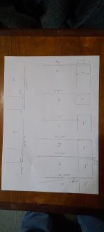
The other day I started thinking of ways to mount the Ali panel.
And was reminded of the mounting of my ply panels.
A.
Was the mounting I used for my large 6ft ply panels.
B.
Is the canvas mounting.
C.
Was the mounting I wanted to use for my ply panels, but I did not have a router.
D to H are various ways to mount the aluminium sheet panels.
But F shows the problem I have with A mounting.
You loose an inch or two at the edges ,plus this method makes the panel edges much stiffer.
The panel tends to bend further into the panel as shown in fig F.
This could make the panel much stiffer than wanted.
And the foam ideas might over damp the panel .
Would it be better to have the foam in fig G on the inner edge and let the outer edge vibrate freely?
Or mounted with foam at say half way between the exciter and outer edge?.
Am I over thinking this.
I like the idea of B C and E having a little bit of rotation in their mounting, giving the panel a bit more flex but holding it firmly.
I will have to think on it more.
Steve.
Attachments

Christian, Hilbren,
I think the measurements below show pretty well the "wave speed" effect you have been looking for.
I did basically the same experiment as Christian did, but using one of my high aspect ratio panels. This was a 20 cm x 93 cm fiberglass/balsa composite panel, mounted to a frame around its perimeter with a soft foam mounting tape.
I placed the exciter 5 cm from one end on the central axis of the panel. The first measurement was made with the mic placed close to the panel (about 2 mm), directly in front of the center of the exciter. In the second measurement, I moved the mic to the other end of the panel, 5 cm away from the opposite edge of the panel, and hence 83 cm from the exciter.


The vertical ridges correspond to the natural frequencies of the panel. As I have noted in other posts, the high aspect ratio panels have a series of closely and regularly spaced natural frequencies which is clearly evident. The lowest frequency ridge at about 94 Hz is actually the 1,3 mode. The fundamental (70 Hz) and 1,2 (81 Hz) are not evident because the exciter is too close to the panel edge to effectively drive those modes.
But most interestingly, the first measurement shows virtually zero delay over the entire frequency range. While in the second measurement, with the mic 83 cm away from the exciter, there is significant delay at low frequencies and which steadily decreases at higher frequencies, exactly as it should. Using the wave speed equation I showed in a recent post, and my best estimates of the modulus, thickness and density of the panel, I calculated an expected delay of about 22 ms at 94 Hz, which is quite close to the measured delayed at that frequency (about 20 ms).
I did the same test with my 30 cm x 120 cm poplar panel, and got similar results (below). In this case the exciter and mic were placed 10 cm from the panel edges. The natural frequencies of this panel are a bit higher, with the 1,3 mode (again the lowest mode evident) being at 130 Hz. Exactly as for the other panel, there is no delay when the mic is located at the exciter, but a significant delay when the mic is moved to the opposite side, 1 meter away in this case. Again, using my best estimates of the plate properties, I calculated an expected delay of 15 ms at 130 Hz, which is pretty much exactly what the measurement shows for the delay at that frequency.
I'd like to repeat the experiment with a less stiff panel, which should have a significantly longer delay. I'll have to see what I can find to try...
Eric


I think the measurements below show pretty well the "wave speed" effect you have been looking for.
I did basically the same experiment as Christian did, but using one of my high aspect ratio panels. This was a 20 cm x 93 cm fiberglass/balsa composite panel, mounted to a frame around its perimeter with a soft foam mounting tape.
I placed the exciter 5 cm from one end on the central axis of the panel. The first measurement was made with the mic placed close to the panel (about 2 mm), directly in front of the center of the exciter. In the second measurement, I moved the mic to the other end of the panel, 5 cm away from the opposite edge of the panel, and hence 83 cm from the exciter.
The vertical ridges correspond to the natural frequencies of the panel. As I have noted in other posts, the high aspect ratio panels have a series of closely and regularly spaced natural frequencies which is clearly evident. The lowest frequency ridge at about 94 Hz is actually the 1,3 mode. The fundamental (70 Hz) and 1,2 (81 Hz) are not evident because the exciter is too close to the panel edge to effectively drive those modes.
But most interestingly, the first measurement shows virtually zero delay over the entire frequency range. While in the second measurement, with the mic 83 cm away from the exciter, there is significant delay at low frequencies and which steadily decreases at higher frequencies, exactly as it should. Using the wave speed equation I showed in a recent post, and my best estimates of the modulus, thickness and density of the panel, I calculated an expected delay of about 22 ms at 94 Hz, which is quite close to the measured delayed at that frequency (about 20 ms).
I did the same test with my 30 cm x 120 cm poplar panel, and got similar results (below). In this case the exciter and mic were placed 10 cm from the panel edges. The natural frequencies of this panel are a bit higher, with the 1,3 mode (again the lowest mode evident) being at 130 Hz. Exactly as for the other panel, there is no delay when the mic is located at the exciter, but a significant delay when the mic is moved to the opposite side, 1 meter away in this case. Again, using my best estimates of the plate properties, I calculated an expected delay of 15 ms at 130 Hz, which is pretty much exactly what the measurement shows for the delay at that frequency.
I'd like to repeat the experiment with a less stiff panel, which should have a significantly longer delay. I'll have to see what I can find to try...
Eric
That's why I asked, the same problems happen on all models of your exciter.I just made these two measurements of my Ali panel at 60cm, but it is the same from 3m.
Pic 1.
From the front.
pic 2.
from the back.
This panel suffers quite badly from the rear, not all panel will be as bad.
I did I believe, make a recording not so long ago of the noise produced from the back and front of some panels ?
It is a little difficult to separate the noises, cavity, coil area, and exciter suspension , plus the hole in the magnet.
I can minimise the first two but not the suspension and exciter vibrating in sympathy with the coil and panel.
This is why I would love to try a powerful piezoelectric thin film an the front of a panel.
You could drive the front surface without a large magnet and suspension in the way.
I agree that the main driving surface at the back of the panel sounds much better than the front secondary driving surface.
But the exciter itself is the main problem, which I can only try and minimise.
Steve.
I've got "suspension and exciter vibrating in sympathy with the coil and panel" on the DAEX25FHE-4. But others I can't hear these. Or maybe too minor that not bother my listening.
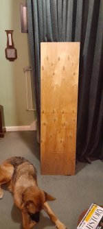
I used bolts system to attach the spine on frame. I can adjust the height of the exciter so pressure is not really a problem. However the horizontal is more difficult to solve (softness of wood, uneven frame width etc).Maybe a pecture will show how easy it is really.
This is a picture of my canvas only panel which has to have a back bracing as the canvas cannot support the exciter.
The method is the same as with a ply panel attached.
I just lay the panel down onto a flat surface and glue the exciter into position.
I place the wood bracing on top of the exciter, and find odd pieces of wood to fill the gaps between frame and bracing.
I found it handy to turn the wood over a few times as a slight bow in the wood can make a big difference and help line things up.
If you have a gap , you could always fill this with silicone or pva or a harder filler.
Or you could do this at the sides where the frame and bracing meet , but I would probably have the bracing going down the panel to stop sagging if silicone was used.
There is a little bit of play( forward and backwards) in the canvas, which is handy ,as this does not put any strain on the coil , and allows the coil to move freely.
You should not be able to see an imprint of the coil or ply panel on the front of the canvas, it should look flat.
As in the photos
Steve.
On future, I think I should use 2 bolts instead of 1 on a side. This may give more level adjustment ability.
When the day I finalized my canvas I will consider the spine again. But now, easy to change exciter is more important for me.
Last edited:
Hello SteveI just made these two measurements of my Ali panel at 60cm, but it is the same from 3m.
Pic 1.
From the front.
pic 2.
from the back.
This panel suffers quite badly from the rear, not all panel will be as bad.
I did I believe, make a recording not so long ago of the noise produced from the back and front of some panels ?
It is a little difficult to separate the noises, cavity, coil area, and exciter suspension , plus the hole in the magnet.
I can minimise the first two but not the suspension and exciter vibrating in sympathy with the coil and panel.
This is why I would love to try a powerful piezoelectric thin film an the front of a panel.
You could drive the front surface without a large magnet and suspension in the way.
I agree that the main driving surface at the back of the panel sounds much better than the front secondary driving surface.
But the exciter itself is the main problem, which I can only try and minimise.
Steve.
Interesting. Like if this material emphasizes some phenomena at the rear. With my plywood panel, I found a peak on the rear wave if I remember around 2kHz. Using the mic at proximity, the "source" was located at the edge of the square piece supporting the exciter like if the exciter area works like a horn.
Have you tried this method?
Since we started to discuss about the "exciter noise", I have been thinking about a countermeasure. One idea is to increase the voice coil length. As I am not in idea to increase the voice coil weight... no obvious solution. Some weeks ago, I saw the cap of a perfume bottle. It is a very thin aluminum cylinder of a diameter similar to voice coil one. Not tested yet. Still in the do list... So if you have this kind of things and if you are attracted by the idea... Please.
Additional hint? gluing some balsa around the cylinder to avoid potential modes?
Christian
Very clean and nice spectrograms in addition to be a bridge between theory and reality. Excellent Eric.Christian, Hilbren,
I think the measurements below show pretty well the "wave speed" effect you have been looking for.
I did basically the same experiment as Christian did, but using one of my high aspect ratio panels. This was a 20 cm x 93 cm fiberglass/balsa composite panel, mounted to a frame around its perimeter with a soft foam mounting tape.
I placed the exciter 5 cm from one end on the central axis of the panel. The first measurement was made with the mic placed close to the panel (about 2 mm), directly in front of the center of the exciter. In the second measurement, I moved the mic to the other end of the panel, 5 cm away from the opposite edge of the panel, and hence 83 cm from the exciter.
View attachment 1093515 View attachment 1093516
The vertical ridges correspond to the natural frequencies of the panel. As I have noted in other posts, the high aspect ratio panels have a series of closely and regularly spaced natural frequencies which is clearly evident. The lowest frequency ridge at about 94 Hz is actually the 1,3 mode. The fundamental (70 Hz) and 1,2 (81 Hz) are not evident because the exciter is too close to the panel edge to effectively drive those modes.
But most interestingly, the first measurement shows virtually zero delay over the entire frequency range. While in the second measurement, with the mic 83 cm away from the exciter, there is significant delay at low frequencies and which steadily decreases at higher frequencies, exactly as it should. Using the wave speed equation I showed in a recent post, and my best estimates of the modulus, thickness and density of the panel, I calculated an expected delay of about 22 ms at 94 Hz, which is quite close to the measured delayed at that frequency (about 20 ms).
I did the same test with my 30 cm x 120 cm poplar panel, and got similar results (below). In this case the exciter and mic were placed 10 cm from the panel edges. The natural frequencies of this panel are a bit higher, with the 1,3 mode (again the lowest mode evident) being at 130 Hz. Exactly as for the other panel, there is no delay when the mic is located at the exciter, but a significant delay when the mic is moved to the opposite side, 1 meter away in this case. Again, using my best estimates of the plate properties, I calculated an expected delay of 15 ms at 130 Hz, which is pretty much exactly what the measurement shows for the delay at that frequency.
I'd like to repeat the experiment with a less stiff panel, which should have a significantly longer delay. I'll have to see what I can find to try...
Eric
View attachment 1093519 View attachment 1093520
I was in the idea to test the material more in the shape of a beam. You did it.
2 questions :
- how the panels in those tests are suspended (I am not sure to understand in the proper way the beginning of the post)?
- which type of mic and REW setting (more precisely the timing box in upper right part of the measurement box)?
The resonant peak on my canvas crate ply is at about 3k, this will vary depending on panel material and internal damping.Hello Steve
Interesting. Like if this material emphasizes some phenomena at the rear. With my plywood panel, I found a peak on the rear wave if I remember around 2kHz. Using the mic at proximity, the "source" was located at the edge of the square piece supporting the exciter like if the exciter area works like a horn.
Have you tried this method?
Since we started to discuss about the "exciter noise", I have been thinking about a countermeasure. One idea is to increase the voice coil length. As I am not in idea to increase the voice coil weight... no obvious solution. Some weeks ago, I saw the cap of a perfume bottle. It is a very thin aluminum cylinder of a diameter similar to voice coil one. Not tested yet. Still in the do list... So if you have this kind of things and if you are attracted by the idea... Please.
Additional hint? gluing some balsa around the cylinder to avoid potential modes?
Christian
Some panels radiate this freely, some like the proplex panel show very little of this problem , but it is still radiated from the back.
The 3k peak I believe is the cavity noise, but there could also be a coil resonance problem too?
Making this area bigger will lower the resonant frequency , making it smaller, will raise the frequency.
Having a fabric dome venting this area would minimise this problem , or even a phase plug.
My preference is the fabric dome (so far) as it still gives some output from the central area.
But this is not always practical on thicker panel materials.
I have always suspected that the sticky rings used to glue on the exciters helps to damp these noises, but this is a blanket damping that damps everything including frequency response.
I prefer not to use damping if possible, as this causes a softening of the sound robbing the panel of dynamics.
Steve.
Ps.
I'm sure I did make a recording of the 3k peak noise from the back and front of one of my panels ?
Easily audible noise.
There is also the problem of how hard you have to drive the exciter to produce sound.
EPS for instance only needs a few Watts to drive it to very loud volumes, the exciter is hardly moving.
To drive an ordinary 3mm ply panel to these volumes, my exciters would be reaching their limits.
The exciter noise will be far greater at these limits.
The mechanical noise produced by cone basket drivers is well known , exciters are no different.
Which is why I still keep an eye out for a piezoelectric solution to drive my EPS panels.
I have been tempted with a few options, but it means spending money on amplification as well.
Steve.
Thanks, yeah I think it's pretty cool too.Very clean and nice spectrograms in addition to be a bridge between theory and reality. Excellent Eric.
I was in the idea to test the material more in the shape of a beam. You did it.
2 questions :
Seems we can also see the wave coming back
- how the panels in those tests are suspended (I am not sure to understand in the proper way the beginning of the post)?
- which type of mic and REW setting (more precisely the timing box in upper right part of the measurement box)?
The two panels were suspended slightly differently, but both are suspended essentially with simple supports around the entire perimeter.
Both are attached by thin double sided foam mounting tape to a stiff wood frame. In the case of the plywood panel, the tape is "3M Extreme", about 1 cm wide and runs around the entire perimeter, except for about 5 cm in each corner. This tape is somewhat firm, and also pretty high damping. For the fg/balsa panel, I wanted to minimize damping, so I used a tape with much lower damping (3M Indoor) and used only a small piece (about 4 mm x 12 mm) every 5 cm around the perimeter. So these two suspensions provide different levels of damping, but are similar in that they are approximately equivalent to "simple" (hinged) supports.
As I have noted before, this method of support, combined with a high aspect ratio panel, provides a nice close series of natural frequencies, particularly just above the fundamental. This works nicely for this experiment, I think. I did try one test with a similar long panel but supported only by it's short ends, and free along the two long sides. But in that case the spacing of the natural frequencies is large, and the results where simply not as clear as in the two results I shared. I see now that I didn't even save those files.
For timing I used the loopback setting.
Mic is the DA iMM-6, probably the cheapest measurement mic you can find!
And yes, I agree, it seems we can see the wave coming back. In fact, in both mic positions. Interestingly, I noticed that the appearance of the spectrograms changes pretty significantly depending on which frequency resolution you choose. In the spectrograms I shared, I used 1/12 resolution. Using 1/12 or 1/24 resolution really emphasizes the natural frequencies. But if you use lower resolution (e.g. 1/6), the reflections start to become even more obvious.
Eric
Eucy,And the effect of the differences in long and cross grain velocity, and the differences in the percentage of long and cross grain material in 3 ply vs 5 ply etc.
All in all a very complex set of circumstances.
Eucy
That's what makes it even more fun!
But honestly, I'm not sure it's quite that complicated. To predict wave speed, I don't think we really need to know details like the percentage of long and cross grain, or even the number of plies. All we really should need is the effective elastic moduli and density of the finished plate. Density is easily measured with a scale and calipers, and the effective elastic moduli can be deduced by various methods, including using the the impulse (tapping) method I described here:
https://www.diyaudio.com/community/...xcitation-for-dml-design-and-analysis.383567/
That said, I admit I don't know exactly how to calculate wave speed in an anisotropic plate. I do find it interesting that wave speed is proportional to stiffness only to the 1/4 power. Which means that a 16x increase in stiffness results in only a doubling of wave speed.
Eric
Hello Eric,Thanks, yeah I think it's pretty cool too.
The two panels were suspended slightly differently, but both are suspended essentially with simple supports around the entire perimeter.
Both are attached by thin double sided foam mounting tape to a stiff wood frame. In the case of the plywood panel, the tape is "3M Extreme", about 1 cm wide and runs around the entire perimeter, except for about 5 cm in each corner. This tape is somewhat firm, and also pretty high damping. For the fg/balsa panel, I wanted to minimize damping, so I used a tape with much lower damping (3M Indoor) and used only a small piece (about 4 mm x 12 mm) every 5 cm around the perimeter. So these two suspensions provide different levels of damping, but are similar in that they are approximately equivalent to "simple" (hinged) supports.
As I have noted before, this method of support, combined with a high aspect ratio panel, provides a nice close series of natural frequencies, particularly just above the fundamental. This works nicely for this experiment, I think. I did try one test with a similar long panel but supported only by it's short ends, and free along the two long sides. But in that case the spacing of the natural frequencies is large, and the results where simply not as clear as in the two results I shared. I see now that I didn't even save those files.
For timing I used the loopback setting.
Mic is the DA iMM-6, probably the cheapest measurement mic you can find!
And yes, I agree, it seems we can see the wave coming back. In fact, in both mic positions. Interestingly, I noticed that the appearance of the spectrograms changes pretty significantly depending on which frequency resolution you choose. In the spectrograms I shared, I used 1/12 resolution. Using 1/12 or 1/24 resolution really emphasizes the natural frequencies. But if you use lower resolution (e.g. 1/6), the reflections start to become even more obvious.
Eric
OK so double side tape all round, which are the conditions you target for the panel.
About the mic setup, how do you sent the reference signal to the sound card? Some schematic of my set up to come... I would like to see what are the other possibilities.
About the appearance of the spectrogram, I don't know what are your knowledge about time to frequency transformation like the wavelets but the key point is it is not possible to be precise on the time scale and on the frequency scale. So changing the 1/n octave of the wavelet change the view. 1/12 is thin in frequency and large in time, 1/6 is a bit wider in frequency but then more precise in time. So 1/12 helps to see the modes, 1/6 helps to see the reflections in time.
Trying to make so example with REW to explain that, I found a cool function of REW that I didn't know : the possibility to make slice in the spectrogram in the time direction. With that we have an idea of the shape of the envelop of the wavelets.
I have for test a wave file of a pure pulse (Dirac) this to check the tools (the expected spectrum is flat.
The IR
The FR
The spectrogram 1/6 oct. Have a look to the control box : frequency axis is in Y axis so the slice is in time (when frequency is in X, the slice is in frequency)
Here the slice is at 6kHz
The same in 1/12
Thinner in frequency (more selective), wider in time...
I have not found for now information about the wavelets used by REW.
The wavelet with the best compromise time, frequency are with a gaussian shape.
Changing the vertical scale from dB to % gives that (see below). So possibily a gaussian wavelet
Christian,About the mic setup, how do you sent the reference signal to the sound card? Some schematic of my set up to come... I would like to see what are the other possibilities.
About the appearance of the spectrogram, I don't know what are your knowledge about time to frequency transformation like the wavelets but the key point is it is not possible to be precise on the time scale and on the frequency scale...
Previously I have no experience with the transformations like wavelets so it is all new to me. I appreciate your example.
Regarding your question about sending a reference signal to the sound card. I do worry that I may not be doing things right. But I am doing nothing myself other than choosing from the timing choices provided on REW. I am not doing anything to send a reference to the sound card other than whatever is built-in to REW. Should I be?
In the measurements I posted, I used the choice: "use loopback as timing reference".
This morning I tried using the other four choices available:
acoustic timing reference (0 ms/0 dB)
no timing reference, 0=IR start
no timing reference, 0= IR peak
no timing reference, 0= Delay estimate
Generally, I saw very little difference, maybe a shift of 1 or 2 ms, but no more. The results with the "acoustic timing reference" and "no timing reference, 0=IR start" both gave results that were slightly more in line with my expectations than the other three options. Those two showed some small delay at 2 kHz at 1 meter exciter to mic distance, while the other three showed the delay at zero there.
I'm interested in any thoughts you have about the various timing reference options.
Eric
Eric,Christian,
Previously I have no experience with the transformations like wavelets so it is all new to me. I appreciate your example.
Regarding your question about sending a reference signal to the sound card. I do worry that I may not be doing things right. But I am doing nothing myself other than choosing from the timing choices provided on REW. I am not doing anything to send a reference to the sound card other than whatever is built-in to REW. Should I be?
In the measurements I posted, I used the choice: "use loopback as timing reference".
This morning I tried using the other four choices available:
acoustic timing reference (0 ms/0 dB)
no timing reference, 0=IR start
no timing reference, 0= IR peak
no timing reference, 0= Delay estimate
Generally, I saw very little difference, maybe a shift of 1 or 2 ms, but no more. The results with the "acoustic timing reference" and "no timing reference, 0=IR start" both gave results that were slightly more in line with my expectations than the other three options. Those two showed some small delay at 2 kHz at 1 meter exciter to mic distance, while the other three showed the delay at zero there.
I'm interested in any thoughts you have about the various timing reference options.
Eric
For the cleanest measurements involving time, I think an external reference is needed.
Here as the speed of HF waves is very high, the error is probably low.
I will try to attach clarify that later on.
Christian
Steve,The other day I started thinking of ways to mount the Ali panel.
But F shows the problem I have with A mounting.
And the foam ideas might over damp the panel .
Would it be better to have the foam in fig G on the inner edge and let the outer edge vibrate freely?
Or mounted with foam at say half way between the exciter and outer edge?.
Am I over thinking this.
I like the idea of B C and E having a little bit of rotation in their mounting, giving the panel a bit more flex but holding it firmly.
I will have to think on it more.
Steve.
I don't believe you are overthinking this a bit.
What is the thickness of your Aluminum panel? And what size are you thinking of? One nice thing about aluminum compared to most of our typical panel materials is that the material properties are well known, and simple (isotropic), so modelling an aluminum plate is much easier than other materials.
Your sketches A and D and F all are pretty much what engineers call clamped (or cantilevered, or "built-in") supports.
C and E are what engineers call simple (or hinged) supports.
G and H are kind of in between, depending on how firm the foam is, how thick it is, how wide it is, and (in the case of H) how far apart the two strips are.
I have played around with "clamped" edges (like A and D) with plywood panels, and have yet to find any good reason to use them. The main problem is the one you raise: It stiffens the panel considerably, in effect, making it act more like a smaller (much smaller in fact) panel, with no compensatory benefit. It's a double hit on the size, in fact. You lose the 1" or whatever that's actually clamped, and then stiffen what's left in the middle. I expect going from simple supports to clamped supports will increase the panel's fundamental frequency by a factor of between 2 and 3.
Simple supports (like C/E) give the benefits of "constrained" edges (i.e. boosting low frequency output), without wasting panel area. I've thought about trying a routed channel (like your "C"), but I think it would be hard make the fit of the panel in the channel so perfect that it acts as a hinge, but doesn't rattle. Your "E" would probably be easier to execute.
That said, I favor G. If you choose the right soft foam, and use a narrow strip, it can approximate a pure simple support very well. One foam tape I have found that provides virtually no damping is this one, especially if you use only a narrow strip.
https://www.lowes.com/pd/Scotch-Mou...Viv_ICh1r4wnKEAQYASABEgKlq_D_BwE&gclsrc=aw.ds
And if you want more damping, try this:
https://www.lowes.com/search?searchTerm=3m extreme scotch double sided tape
Eric
Hi Eric.
A. was the method I used for my rigidly mounted ply panels, I had one at 3ftx2ft and 2 at 6ftx2ft ,one of the 6ft panels used 3mm mdf.
These were full range down to 40hz, but my exciter was at its limits driving these panels.
I did try making a smaller panel but as you say it was too rigid and sounded bad.
I have thought of mounting the 3ft panel on the wall with sound insulation at the back to see if it sounded similar to the stud wall ?
The aluminium is very thin and is 2 sheets glued together, they are actually printing plates.
Two of then glued together is still not quite 0.5mm.
Gluing the two together does stiffen the panels slightly but mostly it is the damping of the usual ringing that is good about this panel.
I xo this at about 120hz at the moment but it is at its limits volume wise.
The panel needs mounting somehow to stop it flexing so much.
I could just xo higher but I want to see how low it can go if mounted correctly.
Holding the sides in my hands does not seem to alter the sound in a bad way, unlike some other materials I have tested.
I'm just curious how it will sound, I'm thinking of this is as more of a bendingwave panel than a dml ?
Or at least somewhere in between.
Steve.
Steve,
Yeah, the method A (clamping) is fine if the panels are that large, I don't doubt.
The two layer aluminum is interesting. Certainly that has the potential to be a well damped panel if the glue layer is indeed a good damper. What is the glue? Did you glue it yourself or did it come to you that way? What size are your aluminum panels? That thin, they probably don't need to be very large.
But yes, aluminum will be hard to drive to high volumes, I expect. I expect it might be similar to the mdf in that respect.
You know I'm a fan of panels with a high aspect ratio, like 3.5:1 or higher. Have you tried any like that?
Eric
Eric.Late last night I suddenly decided to make up a thin sheet aluminium panel ,it is approx 10x13inches and less than 1cm thick.
I glued 2 sheets together with Evo-stik as the spray mount had gone off over the years .
The Evo-stik was getting pretty old as well and was not as thin as it used to be.
But it did the job.
I used it to glue on the exciter too, as I was in a hurry, it was getting late.
Pic 1 is the panel.
Pic 2 is the response at 3m.
Pic 3 is with the TLs xo at 220hz.
Pic 4 is the panel at 1m.
The panels will be xo at 90hz as this exciter has problems with rubbing coils.
You could get away with a 160hz sub roll off, I think.
In my room anyway.
Steve.
The original large aluminium plate I made years ago used spray mount to glue them together .
Yes I did some measurements on this 5mm x5ft x 16inches similar to burnts tall blondes.
As usual I can't find the posts, they are buried in this long thread.
Steve.
Attachments
Eric.
This panel is to satisfy my curiosity about the large aluminium panel I used to have.
I always wondered if used in a smaller size whether this material would perform better?
I'm not saying it will , but I will give it a go.
I was hoping to get the response down to near the 100hz area to make for a good xo point .
So it only has to go down a few hundred more hz without problems.
In the recording I made I was bringing in the TLs at 250hz and rolling off the aluminium panels at 130hz.
This was OK as long as I did not push them too hard.
The old large panel was over damping itself and most sound came from the exciter area, more like a bendingwave panel.
This is what I would call a lossy panel, with not a lot of edge reflections.
I'm hoping the smaller panel with clamping or mounting of some sort will increase this , but it sounds OK as it is , I just hope it does not alter the sound in a bad way ?
Steve.
christian.
i made this recording the other day using pink noise and forgot to post it.
it is of the large crate ply , the mic was about 60cm away and i was just turning the panel around from front to back.
hopefully you can hear the around 3k peak exciter coil cavity noise?
a 30mm coil should have a lower frequency than my 25mm coil (larger cavity).
similar to one of those toy whistles that have a plunger to change the frequency.
steve.
Attachments
- Home
- Loudspeakers
- Full Range
- A Study of DMLs as a Full Range Speaker