Steve,I think we are all aware of what happens if two tweeters are placed on the same baffle , you will get comb filtering between the two .
with the tweeters you will get the comb filtering in the air off axis ,which is bad enough.
but with dml the comb filtering is on and in the panel itself .
it is easy to see , by watching the the waves moving up and down the frequency response as you move a microphone between and around the two exciters .
Is there a measurement I could do in the far field to see this effect? If you make measurements close to the panel, of course I agree you will get a different response as you move the microphone around the surface of the panel. But that is true whether you use one, two, or ten exciters. So I don't accept that it indicates anything other than that a dml is, in fact, modal.
Eric

Yes, that's what I see also. I suspect the rectangles serve as both damping, and constraint, similar to (but not precisely) a hinged/simple support.I think we see the same things : the blue colored panel in #4505 is extracted from a Tectonic video and around are my notes. The 4 supports keep locally the panel in its resting plan. The rest of the edges seems moving in the axis perpendicular to the plan and rotates. The rectangle in the center are visible in the drawing. What is their role : spring or damper. Probably both. I assume more damper to limit the wave reflections (no proof of that)
Eric
Eric.
I think you are getting confused with line arrays ,the pro's and con's of which are well documented.
Let's imagine we have 4 or more small separate dml panels in a line array ,but not touching.
If we move left or right the panels are pretty much time aligned .
But from the floor and ceiling it is going to be a mess .
at all frequencies the panels will be mutually conducting similar to normal pistonic line arrays, except we are now dml.
Now if we mechanically join all the panels and exciters together on a single panel ,this changes everything.
At low frequencies we will still have the mutual output of all the exciters working together.
But now because of the mechanical joining of the panels and exciters, as the frequencies increase the exciters will start to fight each other on the surface and in the panel material, causing combing effects and distortion.
This is all happening before any sound is radiated into the air !!
Moving further away will not change or improve the sound , as the damage has already been done on the surface itself.
Maybe my ears are more sensitive to this, I don't know ? But for this reason I believe a single exciter sounds clearer and more coherent to me .
Luckily for other reasons I have never needed to use more than one exciter on my panels, so I have never had to deal with these problems.
I suppose I'm a minimalist when it comes to a dml panel.
The less I do to a panel, the less needs to be done to it !
The tectonic panel has masses done to it(pun intended) to force the response they need to drive a concert hall.
Which works well.
But for me ,listening at home ,even though I haven't heard them , I know I would have a problem with them !!
Steve.
Understanding the true nature of DML is really challenging also that understanding which of our intellectual models are wrong...Steve,
Is there a measurement I could do in the far field to see this effect? If you make measurements close to the panel, of course I agree you will get a different response as you move the microphone around the surface of the panel. But that is true whether you use one, two, or ten exciters. So I don't accept that it indicates anything other than that a dml is, in fact, modal.
Eric
May I suggest...
If the standard model of an array of 2 point sources applies, some nulls (at least level dips) should appear when the mic is out of the axis. The frequency of the first null decreases when the angle increases. Correct?
So why not to choose an angle (30°, more?). Make a test with one exciter and then with 2. Or perhaps if the exciters are on the panel, one measure with only one on, then both
I agree. I have measured these panels on axis and in 10 degree increments from -90 to +90 in both the vertical and horizontal axes. I did not seen any evidence of comb filtering (although I also was not looking for it). I will have to look at the data more closely.Understanding the true nature of DML is really challenging also that understanding which of our intellectual models are wrong...
May I suggest...
If the standard model of an array of 2 point sources applies, some nulls (at least level dips) should appear when the mic is out of the axis. The frequency of the first null decreases when the angle increases. Correct?
So why not to choose an angle (30°, more?). Make a test with one exciter and then with 2. Or perhaps if the exciters are on the panel, one measure with only one on, then both
Steve, is there a particular frequency range I should look at? The exciters are mounted about 6 cm apart, as I recall, which is about as close as they can be. Although I was not actually trying necessarily to put them close together (or not). I just preferred them to both be on the same spine, and for the spine geometry to be simple. It just happened to turn out that having them close together seemed to work well.
Eric
But now because of the mechanical joining of the panels and exciters, as the frequencies increase the exciters will start to fight each other on the surface and in the panel material, causing combing effects and distortion.
This is all happening before any sound is radiated into the air !!
Moving further away will not change or improve the sound , as the damage has already been done on the surface itself.
Maybe my ears are more sensitive to this, I don't know ? But for this reason I believe a single exciter sounds clearer and more coherent to me .
To be sure, the main reason I sometimes use two exciters is simply to bring the impedence from 4 ohms to 8 ohms, rather than to improve the frequency response. I used to think it gave more headroom, but I'm skeptical of that now.
The worst part of using multiple exciters is that there are too many combinations of positions to try! Finding the best place for one is bad enough, but square it or cube it (with three) and now it'll take hours! I can't imagine doing five exciters.
But I'm less sure than you that it is necessarily bad to use multiple exciters. You say the exciters fight each other. I say they just combine in new, different way. If someone was pretty sophisticated about it, for example, they could reduce a peak caused by a particular mode (or set of modes) by poitioning two exciters in such a way as to mitigate them. Or. alternatively, drive particular modes more strongly, if there is a weak response in the area of that particular natural frequency. Or, more simply, just move the exciters around a the same time, and see where the frequency response is best.
And I didn't mean to suggest that measuring further away would "improve the sound" Rather simply that the response measured close, while providing clues to how the system functions (and hence is of great interest) in the end is irrelevant if that resonse produces a good result in the far field, where we actually listen.
Just the fact that moving the mic across the surface changes the frequency response ("waves moving up and down"), doesn't mean that "damage" was done. It just means that different parts of the panel move differently, and that happens with any number of exciters. It's not damage, it's just the nature of a DML.
Now if you are going to say it's something you hear, even if it can't be measured in the far field, well, then I can't really disagree. Perhaps it's like the echo I hear with polystyrene panels, but simply can't find any clear evidence of in measurements.
Eric
Drat. I should have said "comb through the data" instead!I did not seen any evidence of comb filtering (although I also was not looking for it). I will have to look at the data more closely.
If you want 2 exciters but don't want the complication of figuring out placement, why not just connected both at the same point on either side and wire one backwards so that they move in sync. With a thick enough panel and a thin enough exciter, it could be hidden, or you could extend the mounting point rearward with a tube... or an old speaker cone.To be sure, the main reason I sometimes use two exciters is simply to bring the impedence from 4 ohms to 8 ohms, rather than to improve the frequency response. I used to think it gave more headroom, but I'm skeptical of that now.
The worst part of using multiple exciters is that there are too many combinations of positions to try! Finding the best place for one is bad enough, but square it or cube it (with three) and now it'll take hours! I can't imagine doing five exciters.
Edit... although, one could argue - especially since they're so cheap - that it might be best to simply fill the back of the panel with exciters so that the entire panel moves as one unit. I would think that 6" apart should do the trick without having too many exciters. Not much panel resonance to worry about doing that, and would probably improve frequency response at the low and high end.
Hello Christian,
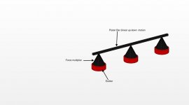
On your post #4505 you show the Tectonic fixation surface waves longitudinal wave front with low frequency at the edges and higher frequencies at the center. The acoustic energy is traveling along the panel which depending on the material is either supersonic or hypersonic velocities in air which at STDP is (344m/s). If you look at that figure and thinking that the amplitude of the surface wave is generating sound that is a transverse wave and does not generate sound in air else one would be hearing sonic booms. For one to generate acoustic wave that one can hear it has to be longitudinal waves ie piston motion of the panel which then the F=ma comes into play and that then limits the high frequency the panel can generate. If you put a MEMS accelerometer on the panel you will see that the panel damps out quickly from the center of the exciter. What you should be considering is a circular to line converter so that the panel acts as a acoustic line source (see attach figure). It is 3D printed and includes the force multiplier which is a shell to reduce it's mass
On your post #4505 you show the Tectonic fixation surface waves longitudinal wave front with low frequency at the edges and higher frequencies at the center. The acoustic energy is traveling along the panel which depending on the material is either supersonic or hypersonic velocities in air which at STDP is (344m/s). If you look at that figure and thinking that the amplitude of the surface wave is generating sound that is a transverse wave and does not generate sound in air else one would be hearing sonic booms. For one to generate acoustic wave that one can hear it has to be longitudinal waves ie piston motion of the panel which then the F=ma comes into play and that then limits the high frequency the panel can generate. If you put a MEMS accelerometer on the panel you will see that the panel damps out quickly from the center of the exciter. What you should be considering is a circular to line converter so that the panel acts as a acoustic line source (see attach figure). It is 3D printed and includes the force multiplier which is a shell to reduce it's mass
Attachments
Further pondering on my previous mention of filling the back of the panel with exciters... given the speed of sound is constant through air, one could use the panel to waveshape. It might be a little complicated and require multiple amp channels. But if you arranged the exciters either vertically or concentrically on a very large, more flexible panel (say 4x8 sheet of 1/4" XPF), you could introduce a slight delay into each successive line/ring that matches the speed of sound.
Heck, at that point, why even use an exciter? You're basically building a very large planar transducer at that point, so might as well just build it from the coils up.
Heck, at that point, why even use an exciter? You're basically building a very large planar transducer at that point, so might as well just build it from the coils up.
Hello Tagis,Hello Christian,
On your post #4505 you show the Tectonic fixation surface waves longitudinal wave front with low frequency at the edges and higher frequencies at the center. The acoustic energy is traveling along the panel which depending on the material is either supersonic or hypersonic velocities in air which at STDP is (344m/s). If you look at that figure and thinking that the amplitude of the surface wave is generating sound that is a transverse wave and does not generate sound in air else one would be hearing sonic booms. For one to generate acoustic wave that one can hear it has to be longitudinal waves ie piston motion of the panel which then the F=ma comes into play and that then limits the high frequency the panel can generate. If you put a MEMS accelerometer on the panel you will see that the panel damps out quickly from the center of the exciter. What you should be considering is a circular to line converter so that the panel acts as a acoustic line source (see attach figure). It is 3D printed and includes the force multiplier which is a shell to reduce it's mass
This is a highly concentrated post!
In think you refer to the second picture of the post #4505 which is an extract of a Tectonic video. The video shows the panel at different frequency and as Spedge mentioned, the displacement in the axis perpendicular to the panel are exaggerated and probably distorted because of the 3D representation. I have no information of the frequency they intent to represent. I keep this in my notes only for the position of the fixations and the suspension on the edges.
Frankly speaking I have some difficulties to fully understand the mechanism of DML.
The academic papers explain the wave speed in the membrane if below the sound speed in the air or above. When they are equal it is the coincidence frequency. The pressure at distance is made by the summation of the speed at each point of the membrane. The relation between the wave speed in the material and the resulting sound is something missing in my understanding. But for sure there is sound, no bang and there is displacement of the panel in the same direction as a piston (except that it is not expected all points move the same distance at the same time).
When you speak about MEMS : have you make something around that show the damping effect in the panel? Is it damped quickly? I am not so sure. We can easily hear the sound at the edge of a large panel, even in a more than 1m plywood.
In your 3D, is the bar intent to "push" the membrane? Have you already test it?
One additional question : why do you name the cone "a force multiplier" ? I am thinking to something similar in order to apply the force more locally but in my understanding the force at the tip of the cone in the one given by the voice coil of the exciter not more.
Christian
My ears are far from good, but have you listened to Matty Hughes speakers? I assume you have. But I can't really hear any distortion from them.Eric.
I think you are getting confused with line arrays ,the pro's and con's of which are well documented.
Let's imagine we have 4 or more small separate dml panels in a line array ,but not touching.
If we move left or right the panels are pretty much time aligned .
But from the floor and ceiling it is going to be a mess .
at all frequencies the panels will be mutually conducting similar to normal pistonic line arrays, except we are now dml.
Now if we mechanically join all the panels and exciters together on a single panel ,this changes everything.
At low frequencies we will still have the mutual output of all the exciters working together.
But now because of the mechanical joining of the panels and exciters, as the frequencies increase the exciters will start to fight each other on the surface and in the panel material, causing combing effects and distortion.
This is all happening before any sound is radiated into the air !!
Moving further away will not change or improve the sound , as the damage has already been done on the surface itself.
Maybe my ears are more sensitive to this, I don't know ? But for this reason I believe a single exciter sounds clearer and more coherent to me .
Luckily for other reasons I have never needed to use more than one exciter on my panels, so I have never had to deal with these problems.
I suppose I'm a minimalist when it comes to a dml panel.
The less I do to a panel, the less needs to be done to it !
The tectonic panel has masses done to it(pun intended) to force the response they need to drive a concert hall.
Which works well.
But for me ,listening at home ,even though I haven't heard them , I know I would have a problem with them !!
Steve.
Just registered because I am interested in building some and really enjoy his setup.
Hello
Please find here an update of the "material graph"
First is the one already posted updated and cleaned D = f(µ)
Second shows a limited number of materials (the one discussed in the last posts). The form is a bit different because it shows the bending stiffness to arial density ratio (D/µ) according to the arial mass µ.
2 vertical axis are added : the coincidence frequency fc Hz and the panel area 1st mode frequency product A.fo.
Thanks to the log log chart and the D/m in vertical, the target for fc or A.fo are horizontal lines.
2 of each are shown : Fc = 5kHz, Fc = 10kHz, A.f0 = 5Hz.m², A.f0 = 15Hz.m2
The line D/µ^3 = 10 or 100 as efficiency criteria are also shown.
The criteria A.f0 is easy to use : for example, with A.f0 = 5, if the target for the 1st mode is f0=40hz then A = A.f0 / f0 = 5/40 = 1/8m² = 0.125m²
How to use that...
In horizontal : to the left the material with the higher efficiency, to the right the material with the lower efficiency
In vertical : up the material with a "low" fc and the need of a larger area to reach low frequencies, down the material with "high" fc and the need of a smaller area.
I would appreciate to have data (bending stiffness) about 10mm EPS, PVA coated or other which in the top list of material choice.
Christian
Eric.
It has been many years since I have used two exciter on any of my panels .
I believe This problem was talked about over on NXT RUBBISH , so I don't really want to go through all those measurements AGAIN.
I don't think I posted my plot anyway ?
But if you have an RTA it is easy to see what happens in real time when moving the microphone between and around the exciters.
The wave I am talking about, is the wave you see on the RTA as you move the microphone between and around the exciters
This wave (or spike , however you want to think of it)will move up and down the frequency range depending on the distance between the exciters .
The tectonic video where they are talking about The OIL CAN affect , within the coil foot area, or primary drive area as he and I have described it.
They expand this area by using 4 exciters the problem is ,now they have 4 oil can affect coils (which isn't a very good description of what is happening in this area) on the the panel.
But now they have created exactly the same conditions which are within the coil area !
You now have 4 exciters competing with each other and waves colliding in peaks and troughs.
If we use the analogy of a single pebble in a pond ? We see the ripples gently moving outward away from the pebble drop.
Now if we drop 4 pebbles into the pond at the same time ,we will see the waves colliding and distorting around the pebble drop area.
it becomes a mess, but a mess that can be controlled somewhat ? by the use of damping and eq ?
This is all happening before DML is set off.
I'm not sure of the distance I had my exciters ,but I presume I might have used the NXT positions on a very large panel.
so the distance was probably more than a few inches ?
When we( I ) am talking far field in my room ,in reality being 10ft from a 7ft panel isn't really far enough.
I am still listening up too close to the large panel surface .
But in a hall similar to the tectonic video I posted you will not hear the panel surface noise.
This is one of the reasons small panels are good for normal sized rooms , small panels less surface area noise .
If you or Christian would like to use your RTA to slowly move your microphone between the two exciters and watch the interference that is created between the two, you might find this enlightening ?
Steve.
Last edited:
Hello SteveEric.
If you or Christian would like to use your RTA to slowly move your microphone between the two exciters and watch the interference that is created between the two, you might find this enlightening ?
Steve.
For sure it might... but 2 exciters or more on one panel if at low priority in what I would like to do. I am more in the "design line" having only one, trying to improve what we have already listed. The possibility to use a second exciter is an idea I have but not close to the main one, it would have a limited band to help in exciting modes in the low frequencies. As I have enough sound level for my use I don't see other needs... my hope even being to increase the efficiency by a more proper material choice.
This remind me that first time I bought exciters I bought also coin exciters with the idea to follow DMLBES advice of a small exciter connected through a capacitor in order to emit the HF. A kind of tweeter. As I am quite happy with the current HF extension... and not fan of any crossover, I haven't tested it. The story doesn't say if the levels of both exciters fit together...
Christian
I just tried with a pair of Polycarbonate plates 500x400x6mm using these chunky exciters:My ears are far from good, but have you listened to Matty Hughes speakers? I assume you have. But I can't really hear any distortion from them.
Just registered because I am interested in building some and really enjoy his setup.
https://www.alibaba.com/product-detail/50-100W-Powerful-8ohm-Flat-Panel_1600078111958.html
So I have similar wattage and similar material, but of course very far from comparable.
I did find that when standing like he has them they sound good and can be driven quite hard. But if I hang them I get ugly resonances with loud bass and need to make some kind of frame to dampen them in some way.
Considering their weight, both acrylic and PC should be quite hard to drive. So you either need multiple exciters or very large ones if you want decent volume.
I think that when placed as Matty done, which is according to Daytons recommendations, they should pretty much work as one large powerful exciter. Maybe better, since larger exciters seems to have less high frequency response.
That's exactly what I was thinking of as well, or close to it. And my next thought was to have a vertical line array of multiple exciters acting on a perpendicular edge glued to aHello Christian,
On your post #4505 you show the Tectonic fixation surface waves longitudinal wave front with low frequency at the edges and higher frequencies at the center. The acoustic energy is traveling along the panel which depending on the material is either supersonic or hypersonic velocities in air which at STDP is (344m/s). If you look at that figure and thinking that the amplitude of the surface wave is generating sound that is a transverse wave and does not generate sound in air else one would be hearing sonic booms. For one to generate acoustic wave that one can hear it has to be longitudinal waves ie piston motion of the panel which then the F=ma comes into play and that then limits the high frequency the panel can generate. If you put a MEMS accelerometer on the panel you will see that the panel damps out quickly from the center of the exciter. What you should be considering is a circular to line converter so that the panel acts as a acoustic line source (see attach figure). It is 3D printed and includes the force multiplier which is a shell to reduce it's mass
Last edited:
Hello Pontos,That's exactly what I was thinking of as well, or close to it. And my next thought was to have a vertical line array of multiple exciters acting on a perpendicular edge glued to a flexible panel that's curved slightly in the middle coming around sharper to the edges with meet perpendicular to the mounting surface (wall). Would that dampen the edge reflections?
DMLs are in an area still to be discovered so fully open to new ideas. It is appealing but in my opinion, it could be also a trap... when I see the difficulties to master a panel with a single exciter! The time and investment to go from the idea to a satisfactory result guide in the choice of the fights. Unless proof that other architectures give easily better or faster results, I think to continue with the single exciter configuration.
About a variable thickness, we can find 2 ideas behind :
- Change the speed of the waves... I don't remember to have seen a document about that. Do you?
- Damping. Here you can see post 969 page 64 about the Acoustic Black Hole. But here also I am at the beginning of the question : is damping good or not?... This question is here independently of the number of exciters.
Christian
- Home
- Loudspeakers
- Full Range
- A Study of DMLs as a Full Range Speaker