But the AB100 is bulletproof, no adjustment required (BIAS only). For me it works great even on a my DIY pcb (at that time original NP PCB was not available) without any testing before building - just LTspice. Accidentally i put 100khz 2V square from signal generator for minute or so ... amp did get very hot but did not burn. And it sounds good - and not as hot as the F5 ... especially on hot summer days. I use existing/salvaged parts (heatsinks, transformres, enclosures) - so it's also an eco-friendly amp.
But the AB100 is bulletproof, no adjustment required (BIAS only). For me it works great even on a my DIY pcb (at that time original NP PCB was not available) without any testing before building - just LTspice. Accidentally i put 100khz 2V square from signal generator for minute or so ... amp did get very hot but did not burn. And it sounds good - and not as hot as the F5 ... especially on hot summer days. I use existing/salvaged parts (heatsinks, transformres, enclosures) - so it's also an eco-friendly amp.
No this is wrong
A bullet proof amplifier should have VI limmiters, thermostats, and protection circuits input and output ....
Clearly the target here is to have very good sound with a minimalistic design to play as good is possible for the specific range and Class and NOT having an amplifier that is bullet proof
Point is that output scheme is clearly outdated and the rest of the circuit is nothing we haven't seen before ....There is not such a thing like innovation in this circuit ...I d say it doesn't match NP we expected more ....
...I d say it doesn't match NP we expected more ....
Nothing stopping you from posting your circuit for us all to admire.
Last edited:
Nothing stopping you from posting your circuit for us all to admire.
I am not a designer But i am a repair man ....East electronics me and my team managed about 2300 audio machines to repair for last year only ...That is a very good number for a small town like Athens in a small country like Greece ... ( that is also the reason you see less of me in the forum )
The above comment might sound a bit like coking, though for this article only useful thing is that after repairing so much then you DO learn all the dirty little secrets about the circuits about the topology and the sound of the semiconductors stability performance and sonic signature .
you actually learn through other ppls mistakes That is why i was expecting more technology and more innovation from NP
Last edited:
Yesterday i had to repair a JVC amplifier .... I remind you that JVC is the first company that implemented New Class A IC in their circuits Please don't ask me if it plays better i am only able to tell you that there is some form of innovation on the circuit ...
Yesterdays JVC consumer class AB receiver had a sigleton in the input not an LTP and also had one op amp before the sigleton to handle the feedback ...First time i have seen a circuit like that
yet again dont ask me if it played better than a "standard" topology Ltp +VAS+driver output or darlington but YES this circuit is innovative in some way
My Integrated Amp coming along
Well i ended up going down a rabbit hole, opening a few cans of worms and then came out the burrow on the other side of the planet!
At first I wanted to control the volume of my "AB100" remotely. (“” because my AB100 is a slightly modified version of NP's; this is DIY audio after all).
I then thought well it would be good to control the input to the amplifier so I can have multiple sources connected.
And then why not think about including a digital receiver and DAC……
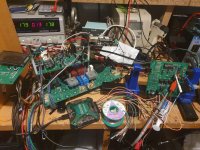
Eighteen months later, twelve prototypes, various DACs, various IV stages amongst others and an extensive “oops” pile and I have finally agreed to a design freeze.
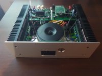
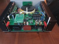
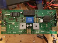
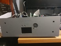
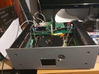
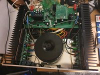
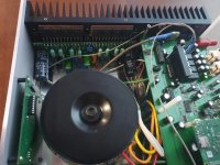
My integrated amplifier utilising the AB100 with volume control, LCD, DC protection, remote control, thermal protection, cooling fans, PCM1798, PCM1906, CS8416 and the option for an embedded Raspberry Pi, Up2Stream or Bluetooth module.
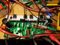
I’m awaiting delivery of the final PCB layouts from JLCPCB to complete the project however here is a pic of the last prototype before ordering the final PCB’s.
Well i ended up going down a rabbit hole, opening a few cans of worms and then came out the burrow on the other side of the planet!
At first I wanted to control the volume of my "AB100" remotely. (“” because my AB100 is a slightly modified version of NP's; this is DIY audio after all).
I then thought well it would be good to control the input to the amplifier so I can have multiple sources connected.
And then why not think about including a digital receiver and DAC……
Eighteen months later, twelve prototypes, various DACs, various IV stages amongst others and an extensive “oops” pile and I have finally agreed to a design freeze.
My integrated amplifier utilising the AB100 with volume control, LCD, DC protection, remote control, thermal protection, cooling fans, PCM1798, PCM1906, CS8416 and the option for an embedded Raspberry Pi, Up2Stream or Bluetooth module.
I’m awaiting delivery of the final PCB layouts from JLCPCB to complete the project however here is a pic of the last prototype before ordering the final PCB’s.
Attachments
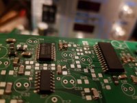
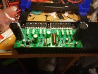
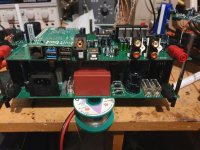
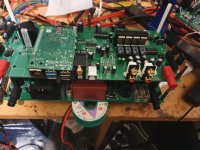
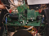
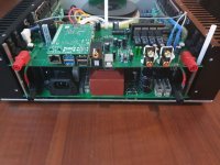
Thanks folks. Here is some more build pics. Albeit it is not the final design (i should have that built in 2 to 3 weeks time  ).
).
).Attachments
-
 20200309_234856.jpg115.8 KB · Views: 291
 -
 20200309_234846.jpg142.3 KB · Views: 277
 -
 20200205_211315.jpg177.2 KB · Views: 295
 -
 20191205_225000.jpg84.3 KB · Views: 314
 -
 20190822_222538.jpg128 KB · Views: 353
 -
 20190822_222528.jpg86.1 KB · Views: 718
 -
 20190819_211333.jpg117 KB · Views: 717
 -
 20190817_184734.jpg131.6 KB · Views: 725
 -
 20190817_184623.jpg146.5 KB · Views: 721
 -
 20190525_102256.jpg144.5 KB · Views: 746
Few more
Attachments
-
 20200310_204208.jpg57.4 KB · Views: 173
 -
 20200310_204203.jpg99 KB · Views: 190
 -
 20200309_235028.jpg129.4 KB · Views: 200
 -
 20200309_235027.jpg129.2 KB · Views: 179
 -
 20200310_204214.jpg114.2 KB · Views: 145
 -
 20200310_204218.jpg102.3 KB · Views: 162
 -
 20200310_212023.jpg99.3 KB · Views: 168
 -
 20200310_212030.jpg117.1 KB · Views: 199
 -
 20200310_212043.jpg119.3 KB · Views: 168
 -
 20200310_212117.jpg111.2 KB · Views: 223
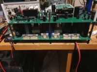
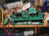
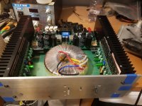
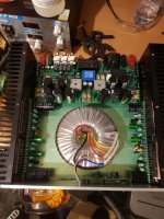
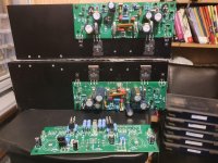
You may also wonder why I didn’t use the original PCB layout and the reason for this was to create my own universal mounting system (sry 6L6). I have now designed and tested several amplifiers with the same heatsink drill pattern; that way i can switch them out for listening tests etc without any great trouble. Here is a pic of a LAT FET amplifier (similar to PeeCeeBee design) and an NP F5 variant PCB partially populated. I also have a Honey badger and SymaSym variant with the same heatsink layout but I haven’t built these yet.
Attachments


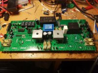
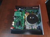
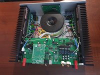
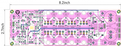
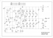
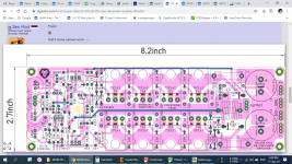
Here is a "DIY PCB" version of AB-100. Can be fitted into case like this
Dissipante 2U – diyAudio Store
I have included output inductor and rail fuses. Also included are the output clamp diodes for reactive loads.
I have a query, if R35 is used as 10ohm Hum Breaking Resistor (HBR), then should R3 value be increased to 330ohms to have correct gain of 36dB as per post #1?
regards
prasi
Attachments
Last edited:
- Home
- Amplifiers
- Pass Labs
- AB100 Class AB Power Amplifier