Are you trying to bring the vertical centres closer together and have you checked the result of that distance yourself? Narrowing the vertical makes the waveguide need to be taller and longer, so you lose out if you take it in this direction.This i due to available baffle space.
Nah, I am trying to bring them further apart.
If I presume a driver total mounting diameter of 28 cm, and produce the waveguide to the same size while the baffle height is limited at 60 cm, I cannot extend C-C much more than 28 cm after subtracting a small margin bottom and top for structural support. When I limit the vertical dimension somewhat, I can extend it a bit more.
If I presume a driver total mounting diameter of 28 cm, and produce the waveguide to the same size while the baffle height is limited at 60 cm, I cannot extend C-C much more than 28 cm after subtracting a small margin bottom and top for structural support. When I limit the vertical dimension somewhat, I can extend it a bit more.
Good news -
Ath 4.8.0 + Application Note 1 regarding using the shaping plugs available for download at https://at-horns.eu
Anyone interested enough can now design their custom device and I hope this will stimulate the experimentation as we need to see more practical realizations. For now it only works in the axisymmetric mode.
Last edited:
I promised to share the 2"/4-vane plug, here it is (full script attached). Of course you can scale it arbitralily.
Code:
SP50 = {
  Dt = 50
  At = 0
  Ae = 31
  L = 95
  Pos0 = 0.2,0.44,0.65,0.84
  ExpRate = 2.7,2.7,2.7,2.7,3.1
  Sk = 0.68
  CP1 = 0.2
  CP2 = 0.5
}
Attachments
Last edited:
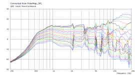
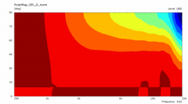
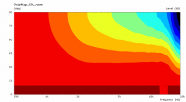
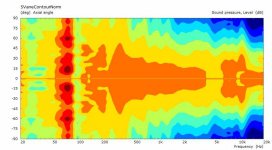
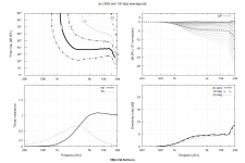
While I was trying to compare two waveguide approaches, I stumbled upon some VACS behaviour which leaves me clueless how I should understand this. It is a axisymmetric device, but as I took the code for graphs from other files, it contains different axis plots. And they do differ, why?
Code:
ABEC.MeshFrequency = 33000
ABEC.NumFrequencies = 100
ABEC.Abscissa = 2
ABEC.SimType = 1
ABEC.SimProfile = 0
ABEC.f1 = 500
ABEC.f2 = 20000

ABEC.Polars:SPL_norm = {
  MapAngleRange = 0,90,19
  Distance = 2       ; [m]
  NormAngle = 10
  Offset = 70
}

ABEC.Polars:SPL_V_norm = {
  MapAngleRange = 0,90,19
  Distance = 2      ; [m]
  NormAngle = 10
  Offset = 70
  Inclination = 90
}

ABEC.Polars:SPL_D_norm = {
  MapAngleRange = 0,90,19
  Distance = 2      ; [m]
  NormAngle = 10
  Offset = 70
  Inclination = 42
}
Attachments

Good to see people getting their hands dirty with the new script ")
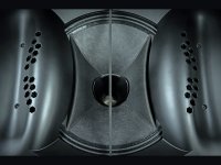
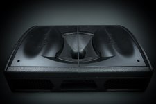
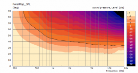
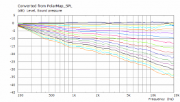
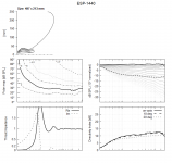
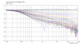
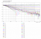
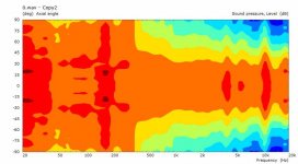
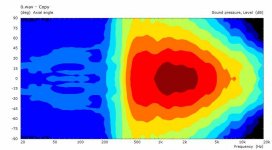
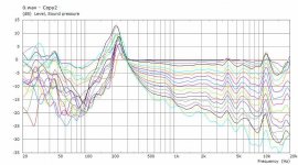
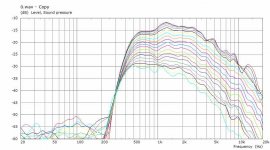
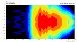
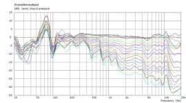
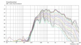
Here is a comparison between the 4 and 5 vane plugs Mabat posted a while back. Both measured on Celestion Axi2050
It's all measured data. The measurements are performed on different days, so there might be a bit of a difference with reflections, however all the plots are made from windowed data.
Here is a comparison between the 4 and 5 vane plugs Mabat posted a while back. Both measured on Celestion Axi2050
It's all measured data. The measurements are performed on different days, so there might be a bit of a difference with reflections, however all the plots are made from windowed data.
Attachments
-
 5and4_FanePlug.jpg345.9 KB · Views: 129
 -
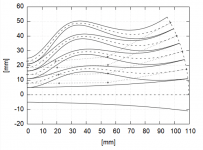
 4vane_Contours_normalized.jpg25.7 KB · Views: 797
 -
 4vane_Contours.jpg26.1 KB · Views: 119
 -
 4vane_Curves_Normalized.jpg57.8 KB · Views: 120
 -
 5vane_Contours_Normalized.jpg29.7 KB · Views: 128
 -
 4vane_Curves_Smoothed.jpg50.8 KB · Views: 128
 -
 5vane_Contours.jpg28.5 KB · Views: 119
 -
 5vane_Curves_Normalized.jpg54.6 KB · Views: 116
 -
 5vane_Curves_Smoothed.jpg52.1 KB · Views: 136
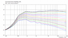
I would say that in this case the 4 vane version is actually quite good for a 2" driver. There is some HF axial ripple similar in both versions which may have something to do with the input wavefront shape, who knows. But why are the two versions so much different at midrange frequencies? Are these different horns or why do you think is that? It's probably not due to a different number of vanes.
Well, maybe it will require a horn with some gradual DI rise in such cases. The plots above look almost DI-flat and that means the absolute SPL falls already quite a lot at HFs because of the big and heavy diaphragm. Do you have an idea about a real sensitivity at say 10 kHz?
While I was trying to compare two waveguide approaches, I stumbled upon some VACS behaviour which leaves me clueless how I should understand this. It is a axisymmetric device, but as I took the code for graphs from other files, it contains different axis plots. And they do differ, why?
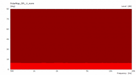
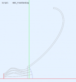
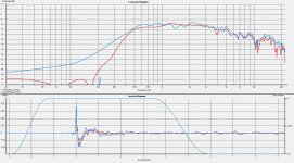
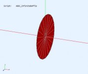
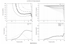
To extend on my recent post, I have tried out both ath 4.7 and beta 5. Ath 4.7 doesnt seem to render the waveguide at all in circ sym mode, probably due to some parameters being off limits for this version, hence, a flat disc. I also attached the clasic report of the waveguide in circular symmetry mode, performing seemingly as intended. But in VCASm the results are as in the recent post. The report hides this. When I instead switch to a full mesh, the result is as in the last attached image. This is kind of troubeling, as if modeling is roling dice. I used the following code:
Code:
Throat.Angle = 10.08
Throat.Diameter = 25.4
Throat.Profile = 1
Coverage.Angle = 43.8

Length = 66
Term.s = 1.11
Term.n = 3.32
OS.k = 0.58
Term.q = 0.99884

;Source.Shape = 2
Source.Shape = 1
Source.Curv = 0
Source.Radius = -1
Source.Velocity = 1


Mesh.LengthSegments = 60
;Mesh.InterfaceOffset = 3

ABEC.MeshFrequency = 33000
ABEC.NumFrequencies = 100
ABEC.Abscissa = 2
ABEC.SimType = 1
ABEC.SimProfile = 0
ABEC.f1 = 200
ABEC.f2 = 20000
Attachments
- Home
- Loudspeakers
- Multi-Way
- Acoustic Horn Design – The Easy Way (Ath4)