Most interesting. I think that I had tried that before (but maybe chose another mode), and I will try it again. If this fails I will need to buy myself another SSD, dedicated to Ath and running Win10. 😵Today I have been able to do it by putting ABEC into Windows 8 compatibility mode. Right click on the desktop shortcut and select compatibility to get to the option. It now solves for me on Windows 11 without any issue and the FRD export works as far as I can tell. This is Maiky's script above.
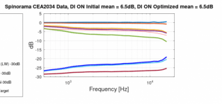
DI is higher on the dotted line below ~2kHz so which ever that is has narrower coverage and the smooth line has wider coverage. I thought "initial" is with the profile with kink, dotted line, and "optimized" is profile without kink, smooth line. Well, easy to mix up as there don't seem to be explicit reference which is which. Anyway, coffee break over 🙂No, the smoother one is wider. At least that is what the individual reports show and I believe it's swapped in the comparison graph.

No, no ABEC projects have solved properly for me on Windows 11 before I changed to compatibility mode today.Did you try with Win11 native?
2m of delay was removed in Ath, that could be tweaked.If the phase on the top right is for 00deg then it seems that there is a +/-4.0mm offset (+/-85deg of added phase @20kHz) compared to the raw output of ABEC or am I missing something?
That happens when the data in the simulation ends and Vituix interpolates down.The LF interpolation/Hilbert (or whatever VCad is doing) does not seem to be trustworthy for far off axis data.
This one (with the sharp outer edge) has the higher, better controlled DI.

(Of which the limit case is a regular R-OSSE profile - it constrains HF from reaching an edge whilst it makes LF as narrow as possible for a given size. It's more ingenious than originally thought. 🙂)
(Of which the limit case is a regular R-OSSE profile - it constrains HF from reaching an edge whilst it makes LF as narrow as possible for a given size. It's more ingenious than originally thought. 🙂)
Last edited:
More coffee 😀 Had to check the individual reports and compare them locally, the profile with kink has higher DI lower in frequency as you say.
It took me while to figure out what you are writing in above post but yeah you are right. Am I correct thinking that you mean with "constrains HF from reaching an edge" that there is no edge? HF in both Maikys examples is the same so the kink has no effect on highs, highs are controlled mostly with profile closer to throat. Highs would indicate diffraction if there was sharp edge, no backside, and you refer to this right?
Yeah as the wavelength is quite different for the LF and HF we are able to optimize both somewhat separately, sliding concept. Since there is much more lows to the mouth and to backside than highs we can concentrate the backside to control guite long wavelengths, relatively sharp edges are fine. Although, sound around the device is much much less than direct sound the control to be gained with interfering the two is not too much. This DI knee control is based on interference, and strong interference needs two strong sounds, which we have not.
You can somewhat direct the sound that initially went around mouth to backside by shaping the backside so that the sound would continue extending from opposite end and not diffract all the way around to continue towards listening window. This would further smoothen the listening window response. It would also narrow the response so "higher DI" on the low knee and listening window smoothness would go hand in hand I think.
Backside size affects path length around the device so affects on frequency you see interference effects on, narrowing of DI. The bigger the backside the longer path length there is around the device and any interference moves lower in frequency. Size and shape go hand in hand as shape has less effect directing the sound the longer the wavelength (path length) so there cannot be as much narrowing on as lows as with diffraction backwave which is kind of a shortcut, polarity flip and possibility to higher SPL and all, stronger interfrence, higher DI 🙂
So the task is to shape the device so that sound is welcomed to the backside of the waveguide but then prevents it going all the way around and toward listening window. This would leave all of the sound expanding outside the listening window making interference and narrowing DI some, while cleaning up interference on listening window, clearing direct sound from all secondary sounds. This will make the cleanest fall graph, but I think it is not possible to reach as much narrowing on coverage on the lows as with diffraction simply because SPL of secondary sound is less.
Last edited:
I think we are in agreement, I just tend to use less words, maybe it's not that well understandable sometimes.
As I see it:
- If you want a low-DI (~5 dB at 1 kHz) waveguide, make the device as smooth as possible all the way back if you want, it can only help, there's no penalty for that.
- If you aim for a higher-DI system, truncate the device as soon as it gives a reasonably smooth FR for high frequencies (for me 0.25 dB ripple is certainly good enough). That will give you the highest DI at the lower end for a given size of the device.
Or something in between 🙂
Last edited:
cool 🙂
And where all this becomes relevant is how waveguide at hand integrates with system at hand.
Basics is that DI of a woofer and a waveguide should match around crossover for smooth transition, smooth system DI. What we affect here with the back side shape is the initial slope of DI of a waveguide, bandwidth where the crossover usually is. Basically, if a waveguide is diffracting on the lows and making extra narrowing on the response one can use similarly diffracting woofer/ baffle for good matching DI. Generalizing even further smoothest crossover happens when shape of both waveguide and woofer construct are the same. On the other hand transducers are very different in size and perhaps there is always some differences around crossover so, as long as DI slopes are roughly similar there should be fine crossover, smooth DI.
Then the question is what is a good trend for system DI? if DI rises rapidly with aid of diffraction does it matter if it happens above or below 1kHz for example? Assuming smooth DI sounds better than one with ripple on it we already know woofer and waveguide need to have matching DI but the next question is how fast we like DI to ramp up, or not? As we are designing waveguides in this thread its good to have in mind what the system DI should be and bake that into the waveguide for smoothest system DI that meets a target, what ever that is.
Last edited:
That's what I said (you just have to know what you want) 🙂As we are designing waveguides in this thread its good to have in mind what the system DI should be and bake that into the waveguide.
- Perhaps the ST260 is already a bit too small for that (rather high) DI. Should I make it again, I would probably make the nominal DI a bit lower. That could ease the integration. Or make the waveguide bigger, of course (which is not what I wanted - the "ST" was for a "Small Teaser", easily printable on the most common 3D printer).
On the comparison graph the curves are color coded to the profile (bottom right corner) blue = initial red = optimized as indicated in the unnormalized networks of responses (top left and center graphs).DI is higher on the dotted line below ~2kHz so which ever that is has narrower coverage and the smooth line has wider coverage. I thought "initial" is with the profile with kink, dotted line, and "optimized" is profile without kink, smooth line. Well, easy to mix up as there don't seem to be explicit reference which is which. Anyway, coffee break over 🙂
View attachment 1131067View attachment 1131068
The dotted lines are for the optimized version in the contours and CEA graph i.e. optimized.
Btw both are results of optimization…
I probably need a better naming convention when I share the graph, sorry for the confusion.
Correct I saw the LF difference and reported it but edited the post because of the difference in diameter…No, the smoother one is wider. At least that is what the individual reports show and I believe it's swapped in the comparison graph.
Last edited:
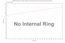
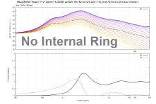
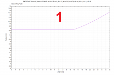
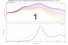
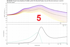
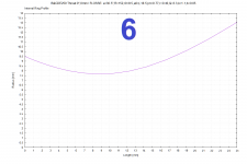
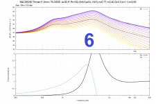
I attempted to simulate custom Internal Rings for the B&C DE250 compression driver for a 30.5 degree horn (a0=15.25). With my crude tools I measured the DE250 conical throat section as 18.5mm diameter entrance with a 25mm diameter exit with a length of 24mm, resulting in a 15.424 degree exit (or 7.712 half angle). That could be wrong because my tools are crude. I simulated for slightly different entrance diameters because I wasn't sure if my measurements were correct and ~6 degree exit angles were given for the DE250 in DIYAudio forum posts. So those could/will be wrong in reality.
1)
Throat.Ext.Angle = 0
Throat.Ext.Length = 16
a0=15.25
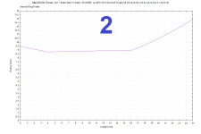
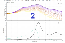
2)
Throat.Ext.Angle = -10.1
Throat.Ext.Length = 4
Slot.Length = 11.5
a0=15.25
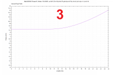
3)
Throat.Ext.Angle = 0
Throat.Ext.Length = 10
a0=0
4)
Throat.Ext.Angle = -2.8
Throat.Ext.Length = 15.5
a0=15.25
5)
Slot.Length = 6
a0=-10 ; (negative 10 angle)
6)
r0 = 11
a0 = -18.5 ; (negative 18.5 angle)
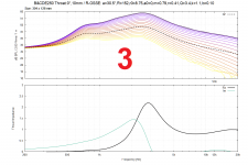
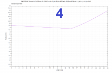
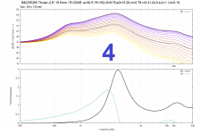
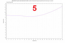


Last edited:
For post https://www.diyaudio.com/community/...-design-the-easy-way-ath4.338806/post-7238240
Here is the impedance report script.
And here is the Internal Ring report script.
Here is the impedance report script.
load 'static.txt'
load 'param.txt'
set terminal pngcairo color size R_W,R_H font "Arial,10"
set output R_FILE.'_Impedance.png'
set multiplot layout 2,1 \
margins 0.1,0.96,0.08,0.93 \
spacing 0.1,0.04 \
title R_TITLE font "Arial,14" noenhanced
set label R_DIM at screen 0.1,0.95 font "Arial,11"
set size noratio 1,1
set border 31
set xtics in auto
set ytics in auto
set xrange [200:20000]
set xtics add ("" 200, "" 500, "" 1000, "" 5000, "" 10000, "12K" 12000, "" 15000, "" 20000)
set logscale x
# raw SPL curves + Sound Power
set grid xtics mxtics ytics
unset colorbox
set yrange [R_MIN_SPL:R_MAX_SPL]
set ytics 5
set ylabel "dB SPL / ".R_VRMS." / ".R_DIST offset 0,0
unset format y
plot "polars.txt" u 1:2:3 not w l lw 1 palette, \
"spower.txt" u 1:2 w l dt "-" lc rgb "black" lw 2 t "SP"
# Throat Impedance
set xlabel "Frequency [Hz]"
set xtics add ("200" 200, "500" 500, "1k" 1000, "5k" 5000, "10k" 10000, "12k" 12000, "" 15000, "20k" 20000)
set yrange [0:3]
set ytics in auto
#set ytics ("0" 0, "0.2" 0.2, "0.5" 0.5, "1" 1, "1.5" 1.5, "2.0" 2, "2.5" 2.5)
set ylabel "Throat Impedance" offset -1,0
plot "radimp.txt" u 1:2 w l lw 2 lc rgb "black" t "Re", "" u 1:3 w l lw 1 t "Im"
unset multiplot
And here is the Internal Ring report script.
load 'static.txt'
load 'param.txt'
set terminal pngcairo color size R_W,R_H font "Arial,10"
set output R_FILE.'_RingInternal.png'
set multiplot layout 1,1 \
margins 0.1,0.96,0.1,0.92 \
title R_TITLE font "Arial,11" noenhanced
set grid xtics mxtics ytics
set label 'Internal Ring Profile' at screen 0.1,0.95 font "Arial,10"
set yrange [0:14]
set ytics 0.5
set ylabel "Radius [mm]"
set xrange [0:25]
set xtics 1
set xlabel "Length [mm]"
plot 'coords.txt' u 1:2 w l lw 1 not, 0 lt 4 not
unset multiplot
Yes, that is how it works. The best is if you don't have to use 'Throat.Ext.Length' at all - that of course depends on the driver used (the more open and shorter the exit section, the better).
This is an 18" driver in a simple open baffle (free air, without a floor).
Seems perfect for 500 Hz crossover to a large horn.


Seems perfect for 500 Hz crossover to a large horn.
Last edited:
I think in practise that is very har to achieve - that is at least my experience - using 8" drivers... but maybe there isa trick..
//
//
Hi,
Is there any point in designing a 3" waveguide for a 5/8" tweeter?
I have this tweeter:
https://www.parts-express.com/Dayto...oft-Dome-Neodymium-Tweeter-275-025?quantity=1
And I want to may a 2 way, pairing it ith a 3" or 3.5" woofer. Any recommendations?
Cheers.
Is there any point in designing a 3" waveguide for a 5/8" tweeter?
I have this tweeter:
https://www.parts-express.com/Dayto...oft-Dome-Neodymium-Tweeter-275-025?quantity=1
And I want to may a 2 way, pairing it ith a 3" or 3.5" woofer. Any recommendations?
Cheers.
I've had a hard time learning Fusion 360 and still find it difficult to translate what I want in something that Fusion understands.
So I tried scripting Fusion 360 using its python API. So far the examples in the documentation have helped a lot. I extended AthProfileImport and hope to end up with a simple method to get a 3d printable throat + petals + 'glue helpers' model.
Here is what I have thus far:
If anyone wants to join in I can put it on github.
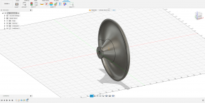
So I tried scripting Fusion 360 using its python API. So far the examples in the documentation have helped a lot. I extended AthProfileImport and hope to end up with a simple method to get a 3d printable throat + petals + 'glue helpers' model.
Here is what I have thus far:
Code:
# Author-Autodesk Inc
# Description-Import Ath4 curves from file

import adsk.core, adsk.fusion, math, traceback

def run(context):
    ui = None
    try:
        app = adsk.core.Application.get()
        ui = app.userInterface
        design: adsk.fusion.Design = app.activeProduct
        if not design:
            ui.messageBox('No active Fusion design', 'Ath Profile Import')
            return
        rootComp = design.rootComponent

        dlg = ui.createFileDialog()
        dlg.title = 'Open Ath Profile'
        dlg.filter = 'Ath Profile Definition (*.afp);;All Files (*.*)'
        if dlg.showOpen() != adsk.core.DialogResults.DialogOK:
            return

        f = open(dlg.filename, 'r')
        sketch: adsk.fusion.Sketch = rootComp.sketches.add(rootComp.xYConstructionPlane)
        lines = sketch.sketchCurves.sketchLines
        points = {}

        line = f.readline().rstrip()
        while line:
            if len(line) < 3 or line[0] == '#':
                line = f.readline().rstrip()
                continue
            items = line.split(' ')
            if line[0] == 'P' and len(items) >= 4:
                points[items[1]] = adsk.core.Point3D.create(
                    0.1*float(items[2]), 0.1*float(items[3]), 0.0
                )
            elif line[0] == 'L' and len(items) >= 3:
                lines.addByTwoPoints(points[items[1]], points[items[2]])

            elif line[0] == 'S' and len(items) >= 3:
                splinePoints = adsk.core.ObjectCollection.create()
                for k in range(int(items[1]), int(items[2]) + 1):
                    splinePoints.add(points[str(k)])
                sketch.sketchCurves.sketchFittedSplines.add(splinePoints)

            elif line[0] == 'U':
                splinePoints = adsk.core.ObjectCollection.create()
                for k in items[1:]:
                    splinePoints.add(points[k])
                sketch.sketchCurves.sketchFittedSplines.add(splinePoints)

            line = f.readline().rstrip()
        f.close()

        # Draw a line to use as the axis of revolution.
        lines2 = sketch.sketchCurves.sketchLines
        axisLine = lines2.addByTwoPoints(adsk.core.Point3D.create(0, 0, 0), adsk.core.Point3D.create(1, 0, 0)) # X axis

        # Get the profile defined by the ath waveguide profile.
        prof = sketch.profiles.item(0)

        # Create an revolution input to be able to define the input needed for a revolution
        # while specifying the profile and that a new component is to be created
        revolves = rootComp.features.revolveFeatures
        revInput = revolves.createInput(prof, axisLine, adsk.fusion.FeatureOperations.NewComponentFeatureOperation)

        # Define that the extent is an angle of pi to get half of a torus.
        angle = adsk.core.ValueInput.createByReal(2*math.pi)
        revInput.setAngleExtent(False, angle)

        # Create the extrusion.
        ext = revolves.add(revInput)

        # Get the body created by the extrusion
        body = ext.bodies.item(0)

        # Create a construction plane by offsetting the end face
        planes = rootComp.constructionPlanes
        planeInput = planes.createInput()
        offsetVal = adsk.core.ValueInput.createByString('8 cm')
        planeInput.setByOffset(rootComp.yZConstructionPlane, offsetVal)
        offsetPlane = planes.add(planeInput)

        # Create SplitBodyFeatureInput
        splitBodyFeats = rootComp.features.splitBodyFeatures
        splitBodyInput = splitBodyFeats.createInput(body, offsetPlane, True)

        # Create split body feature
        splitBodyFeats.add(splitBodyInput)

    except:
        if ui:
            ui.messageBox('Failed:\n{}'.format(traceback.format_exc()))
If anyone wants to join in I can put it on github.

Last edited:
Here is a simulation for zero throat length with 18.5mm diameter throat entrance vs the original factory 24mm long throat (B&C DE250 as close as I can measure with my tools). However, I don't understand what impact impedance has beyond equalization. Do large impedance changes/swings create problems that don't show up in the ABEC simulations, e.g.: high order modes described by Earl Geddes; group delay problems; or something else?
Now that I have a little experience manipulating impedance I don't know what I should be targeting if the compression driver won't allow a zero throat length for my chosen coverage angle.
Now that I have a little experience manipulating impedance I don't know what I should be targeting if the compression driver won't allow a zero throat length for my chosen coverage angle.
Attachments
I think that the impedance that you are talking about is the acoustic impedance seen ay the throat. That's not a problem and isn't a strong parameter anyways. What does matter is how the impedance changes along x - the direction of propagation. Large changes and/or discontinuities will cause diffraction and the creation of higher order modes.Do large impedance changes/swings create problems that don't show up in the ABEC simulations, e.g.: high order modes described by Earl Geddes; group delay problems; or something else?
- Home
- Loudspeakers
- Multi-Way
- Acoustic Horn Design – The Easy Way (Ath4)

