Designing an active Twin-Tee Notch filter to build for amplifier design work.
Features are:
Cheers, Mike
Features are:
- Selectable notch frequency: 1kHz or 10kHz for use with my Victor low distortion oscillators
- Selectable gain: 0dB or 40dB
- Filter bypass switch
- Three front panel trim pots to adjust notch frequency - one for each "R" leg
- BNC and 1/4" audio jack IN and OUT
- Separate output op-amps for BNC and audio jack outputs
- Input voltage protection via 12V TVS bi-directional diode
- Input power: + and - 12VDC, diode protected for reverse polarity
- Filter impedance lowered by 10X for lower noise performance
- Modified the gain switching circuitry after observing noise issues with the breadboard of previous circuit
- Op-amp input protection by TVS diode added
- Power supply protection diodes added
Cheers, Mike
Attachments
Last edited:
Did you try that in real measurements yet? IMO, without the buffer and diff.inputs such filter nearly useless.
Try to simulate that, one DUT is 100ohm Zout, and another one is .1ohm. I rather took a practical Zout range, actually, the max range could be wider like 1000-.05ohm. Are you gonna every time recalibrate the notch??
Try to simulate that, one DUT is 100ohm Zout, and another one is .1ohm. I rather took a practical Zout range, actually, the max range could be wider like 1000-.05ohm. Are you gonna every time recalibrate the notch??
I have breadboarded the circuit and tested it. The filter notch was good for about -90dB at 1kHz, down to -100dB with care at adjustment.Did you try that in real measurements yet? IMO, without the buffer and diff.inputs such filter nearly useless.
Try to simulate that, one DUT is 100ohm Zout, and another one is .1ohm. I rather took a practical Zout range, actually, the max range could be wider like 1000-.05ohm. Are you gonna every time recalibrate the notch??
I do plan to adjust the null each time I use the filter, though my amplifier test setup does not vary. It does not take long to adjust three pots.
I understand your point about the effect of DUT impedance and will look into it's effect on operation.
Right now I'm looking into the effect of filter impedance on output noise. I have measured the output noise with the filter R=7322/C=22nF and will compare that to measurements at R=732/C=220nF soon.
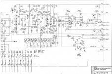
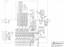
I'm a big fan of borrowing from existing successful designs. Attached is the input buffer and the bridged T notch filter (one of 3) in the Shibasoku 725B. The buffer is complex but has distortion residuals below 130 dB. The notch shows all the bits necessary to make it fully tunable. It also shows details on the active feedback to raise the Q. Building a single frequency version would be far simpler but you still need a good buffer with input protection. The key things to look at are:
The input protection. Substituting lightbulbs for the input resistor gets the noise down while retaining the protection.
The active feedback to optimize the Q. The opamp driving the feedback has the most impact on the residual distortion. I upgraded to the now unobtanium LME49990 there. I don't think a guard amp would be needed, it drives the cans on the 30? relays.
I'm not sure how important the cap neutralizer amp is either.
I think bridged T was selected because there are fewer parts to the tuning. Important when you are doing something this crazy.
Attachments

The disadvantage of a steep, very deep notch is that the source signal must be very tightly controlled in frequency and freq. stability.
What do you want to use it for? Is it to run a DUT signal through so your distortion measurement will be able to look deeper?
In that case, a (passive) notch of say 40dB is much more useable; it has a somewhat wider notch making the source frequency accuracy and stability requirements much more relaxed, while still allowing a HD measurement down to -150dB with a reasonable sound card.
Jan
exactly.The disadvantage of a steep, very deep notch is that the source signal must be very tightly controlled in frequency and freq. stability.
What do you want to use it for? Is it to run a DUT signal through so your distortion measurement will be able to look deeper?
In that case, a (passive) notch of say 40dB is much more useable; it has a somewhat wider notch making the source frequency accuracy and stability requirements much more relaxed, while still allowing a HD measurement down to -150dB with a reasonable sound card.
Jan
I agree that a passive notch filter is easier to use, but am not a fan of the (overly) broad roll-off due to the low Q (0.25 I believe). It rolls off the lower harmonics too much for my intended usage. I would like no more than 1dB of variation in the filter response from the 2nd harmonic upward.
All very interesting points which I will have to look into. I may end up buffering the input before the T after all. Not sureI'm a big fan of borrowing from existing successful designs. Attached is the input buffer and the bridged T notch filter (one of 3) in the Shibasoku 725B. The buffer is complex but has distortion residuals below 130 dB. The notch shows all the bits necessary to make it fully tunable. It also shows details on the active feedback to raise the Q. Building a single frequency version would be far simpler but you still need a good buffer with input protection. The key things to look at are:
The input protection. Substituting lightbulbs for the input resistor gets the noise down while retaining the protection.
The active feedback to optimize the Q. The opamp driving the feedback has the most impact on the residual distortion. I upgraded to the now unobtanium LME49990 there. I don't think a guard amp would be needed, it drives the cans on the 30? relays.
I'm not sure how important the cap neutralizer amp is either.
I think bridged T was selected because there are fewer parts to the tuning. Important when you are doing something this crazy.
Looking over your notes again, I think it might be easiest to simply add in an instrumentation amplifier IC in front of the T-filter to provide a differential input and buffer the filter from the rudeness of input source variations.All very interesting points which I will have to look into. I may end up buffering the input before the T after all. Not sure
Slightly OT:
After so many years here you start to see a pattern: someone details a design, and the rest of the thread is about what the purpose is and how it would be used in practise, and the design is adapted and starts to look more and more like a kludge. Cart before the horse, so to say.
Bruno Putzeys, of nCore and Purifi fame, would put it this way:
"Specify the design and accept the performance - the road to hell;"
"Specify the performance and accept the design - the road to heaven."
For me that aspect is the main difference between an amateur/diyer and a professional.
OT off.
Have a nice weekend you all.
Jan
Disadvantage? Not necessarily. Just tightly control the frequency based on the I/O phase relationship of the twin T filter.The disadvantage of a steep, very deep notch is that the source signal must be very tightly controlled in frequency and freq. stability.
[...]
Jan
I have done this, look here. And it works, even with a notch depth of -120dB.
Jan and IVX's comments got me to circle back and take a closer look at my intended signal source and load hardware. Which would be:Looking over your notes again, I think it might be easiest to simply add in an instrumentation amplifier IC in front of the T-filter to provide a differential input and buffer the filter from the rudeness of input source variations.
Source: AutoRanger II which as a balanced output, source impedance of 47ohms each side.
Load: EMU0404USB Soundcard with a balanced input, impedance of 1Meg each side.
Nicely this eliminates any variations in source impedance.
Plan now is to add a differential amplifier, such as the INA134, in front of the Twin T-Filter (with protection diodes to rails) and a line driver (DRV134) after the gain op-amp to drive a 1/4" balanced output jack. I like it.
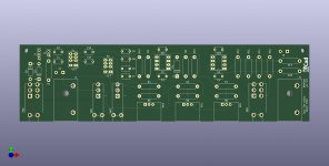
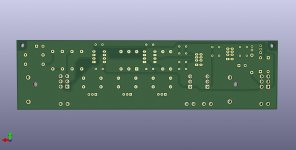
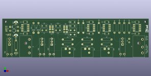
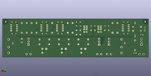
Think I'm done with the design and layout. Decided on Balanced Input and separate Outputs of Balanced and Single-Ended. Plan to use a SilentSwitcher to power it (if they come back in stock).
Attachments
You can use U1A as the gain amp - this saves U2A...Think I'm done with the design and layout. Decided on Balanced Input and separate Outputs of Balanced and Single-Ended. Plan to use a SilentSwitcher to power it (if they come back in stock).
Martin
P.S.: ...or use U2A as an inverter (for negative output, U1A as positive output) and save DRV134.
Some inspiration could be here:You can use U1A as the gain amp - this saves U2A...
https://www.diyaudio.com/community/...perform-apx555b-for-30000.386001/post-7077589
Also, check your R9/R10 values.
M.
You're thinking the R9/R10 values should be ?Some inspiration could be here:
https://www.diyaudio.com/community/...perform-apx555b-for-30000.386001/post-7077589
Also, check your R9/R10 values.
M.
I think that if I did use U1A as a switchable gain stage (40dB/0dB), I would also have to switch the resistors for U2A (R9/R10) to compensate for the change in forward gainYou can use U1A as the gain amp - this saves U2A...
Martin
P.S.: ...or use U2A as an inverter (for negative output, U1A as positive output) and save DRV134.
- Home
- Design & Build
- Equipment & Tools
- Active Twin-Tee Notch filter design