Absolutely! Thanks for chiming in. Always looking for other perspectivesSorry, R9/R10 values are OK (my mistake).
You can leave your design as is - for 40 dB maybe is better to leave gain stage as separate stage.
I like IVX approach in Cosmos APU, so I showed it as inspiration.
M.
I did go back and simplify a few non-critical resistor values for a smaller shopping list.
First I will have to have a set of boards made and evaluate them. Probably order a set of 3 boards from OshPark this week.Hi Mike,
Are you going to publish the Gerber files too, so people can order PCB’s for personal use?
I couldn’t find any, but perhaps I overlooked this?
Regards, Gerrit
I just ordered three boards from OshPark. Once they arrive and I test & evaluate them, I will sell off the extra 2 at cost. Once that is done, I will probably post the KiCad and Gerber files for use by others.First I will have to have a set of boards made and evaluate them. Probably order a set of 3 boards from OshPark this week.
Cheers, Mike
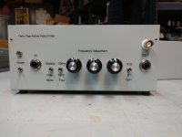
I finished and tested my Twin-Tee active notch filter today. It works just as designed (which is always nice). The sharp notch at 1kHz or 10kHz reaches -60dB easily with adjustment of the three front panel pots. I found that the easiest way to adjust those controls is to observe the filter OUT (Y) vs IN (X) on an analog scope in XY mode. The single-ended BNC output on the filter comes in handy for this while the Balance output can remained connected to the spectrum analyzer.
The Bypass and X100 Gain functions work well, as expected (not much to those circuits).
Note: The Gain control on the front panel picture should be labelled X1 / X100. I need to change that label.
The gain could be set to other than X100 by using different op-amp resistor values.
Anyone interested in buying one of the two remaining PCB's (BOM and schematic included) let me know. An external power source is required (+/-12V).
Cheers, Mike
Attachments
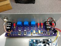
Wait a minute, what is the cap's type did you use in the filter? As I see it is some cheap ceramic caps right? Actually, this is one of the most critical points is choosing the right types of passive parts. I using C0G 100-250V(selected from many different types and manufacturers) 2pcs in serial to get minimal VCC and make sure that my passives H3 limit is around -170db@1kHz. If you took the type that I guess, you got H3 result worse than the bare average ADC does -110-120db@1khz. Resistors are also critical due to VCR but in general, long enough resistor type has quite low VCR, so your looks good enough.I finished and tested my Twin-Tee active notch filter today. It works just as designed (which is always nice). The sharp notch at 1kHz or 10kHz reaches -60dB easily with adjustment of the three front panel pots. I found that the easiest way to adjust those controls is to observe the filter OUT (Y) vs IN (X) on an analog scope in XY mode. The single-ended BNC output on the filter comes in handy for this while the Balance output can remained connected to the spectrum analyzer.
The Bypass and X100 Gain functions work well, as expected (not much to those circuits).
Note: The Gain control on the front panel picture should be labelled X1 / X100. I need to change that label.
The gain could be set to other than X100 by using different op-amp resistor values.
Anyone interested in buying one of the two remaining PCB's (BOM and schematic included) let me know. An external power source is required (+/-12V).
Cheers, Mike
I used my Brother P-Touch label printer with black on clear tape. ThanksNice built Mike! How did you do the labels - printing on clear self-sticking label stock?
Jan
For the filter caps I used TDK C0G 100V FG series ceramic caps.Wait a minute, what is the cap's type did you use in the filter? As I see it is some cheap ceramic caps right? Actually, this is one of the most critical points is choosing the right types of passive parts. I using C0G 100-250V(selected from many different types and manufacturers) 2pcs in serial to get minimal VCC and make sure that my passives H3 limit is around -170db@1kHz. If you took the type that I guess, you got H3 result worse than the bare average ADC does -110-120db@1khz. Resistors are also critical due to VCR but in general, long enough resistor type has quite low VCR, so your looks good enough.
Side note Jan. Will Silent-Switchers still be available? I had planned to use them to power my Twin-Tee filter and to upgrade the power supply on my Cordell Distortion Magnifier. BUT they appear to be out of stock in a big way.I have a P-touch. Didn't know about the clear tape. Good tip!
Jan
I ended up whipping up "fake" Silent Switchers for both instruments (a cheap buck/boost from China followed by a Jung/Didden superreg), but am not happy with the amount of HF noise making it's way to the instrument output (primarily at 180MHz and 240MHz). Targeted bypass caps (68pF) and ferrite beads knocked it down quite a bit, but not totally.
I understand and am not surprised. I will probably whip up a small linear +/- supply to feed the SuperReg's in place of the cheap buck/boost's.Sorry Mike, it is unlikely that silentswitchers will reappear.
Just not viable economically what with sharply increased manu costs and chip shortages.
Jan
Suspecting this I've been toying with the idea of whipping up a "SilentSwitcher" for my own in-house use. I do need to get up to speed on switching tech and that would be a fun project to learn on.
Take care, Mike
- Home
- Design & Build
- Equipment & Tools
- Active Twin-Tee Notch filter design