Allen Wright said:Tico,
Thanks for the data sheet link.
Now, does anyone know how to pull the PDF out of that AllDatasheets mess so I can look at it with Acrobat Reader, and not just my browser which doesn't allow me to expand it enough to see all the graphs?
Regards, Allen (Vacuum State)
right click
save target as
http://www.analog.com/static/imported-files/data_sheets/MAT01.pdf
http://www.analog.com/static/imported-files/data_sheets/MAT02.pdf
http://www.national.com/ds/LM/LM194.pdf
http://www.analog.com/static/imported-files/data_sheets/MAT03.pdf
http://www.analog.com/static/imported-files/data_sheets/MAT04.pdf
john curl said:You agree? Wonderful!
Not only agree; I can even contribute: BJTs are current controlled devices, so used instead of tubes that are voltage controlled devices they will represent a non-linear input resistance (actually, a diode), while we may assume that input resistance of tubes is always stable and equals to the value of a grid leak resistor (however, some Miller capacitance presents, that is variable as well).
What a waste of input power, in case of tubes! They definitely have to produce louder noises! Unless transformer coupled with the signal source... But transformers, like bees and honey, are bad as well...
Allen Wright said:Thanks Hitsware.
I have no problem downloading real PDFs, justthat site doesn't make it easy.
Regards, Allen (Vacuum State)
PS I have no "right" button to click...
the links i posted are from analog devices
they are real pdf
")
Allen Wright said:
PS I have no "right" button to click...
There should be some easy way to save the PDF. 2 days ago I approached Mac in order to switch on projector output and found that it is very simple, though I was afraid it is hard to find using 1 button mouse only.
I have no "right" button to click...
If you're coming to ETF this year, I'll bring a right button with me.
SY said:I'll bring a right button with me.
Warning: Do not install it. It's from the evil Microsoft/IBM empire. Known to cause bad attitudes and even cancerous type ailments in long time users.
Stick with Mac, you'll never go back.
Cal Weldon said:
Warning: Do not install it. It's from the evil Microsoft/IBM empire. Known to cause bad attitudes and even cancerous type ailments in long time users.
Stick with Mac, you'll never go back.
I have to agree: a habit to use 2 or 3 buttons cause a habit to design an equipment that looks like a bird's nest inside, and like a junkyard outside.
Now that Hitsware has put up links: Check out the differences between MAT 01 and MAT02 data sheets, and note the difference in capacitance, and beta linearity. This is why I had to ask Scott Wurcer about his input device characteristics. I am surprised that he could use a MAT 02, because of the input capacitance. Check it out.
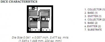
Picture
Here the MAT02 picture.
Allen Wright said:Tico,
Thanks for the data sheet link.
Now, does anyone know how to pull the PDF out of that AllDatasheets mess so I can look at it with Acrobat Reader, and not just my browser which doesn't allow me to expand it enough to see all the graphs?
Regards, Allen (Vacuum State)
Here the MAT02 picture.
Attachments
I have asked several people at AD about the MAT02/SSM2210 process but no one can give me any info.
Did you try the SSM2210 and did it sound as good as the MAT02? Looking at the datasheets the MAT02 is really dual monolithic but the SSM2210 just states "dual matched transistor pair" so it may actually be just two selected chips in a single package.
MRupp said:
Did you try the SSM2210 and did it sound as good as the MAT02? Looking at the datasheets the MAT02 is really dual monolithic but the SSM2210 just states "dual matched transistor pair" so it may actually be just two selected chips in a single package.
The SSM2210 is just a MAT02 in a plastic dip - a lower cost version.
They are monolithic, with parasitic, high capacitance diodes between the collectors and the substrate. These diodes are 70pF each and give a collector-collector capacitance of 35pF (specified on the datasheet).
In some applications, when used as a long tail pair they perform best cascoded, to mitigate the effects of that 35pF.
A bootstrapped cascode will also mitigate the effects of the high Miller (Cob) capacitance.
Cheers,
Glen
john curl said:...between MAT 01 and MAT02 data sheets, and note the difference in capacitance, and beta linearity. This is why I had to ask Scott Wurcer about his input device characteristics. I am surprised that he could use a MAT 02, because of the input capacitance. Check it out.
So what.
Mat01 is probably close to the minimum transistor of the process and Mat02 is fat.
Just compare the voltage noise densities:
Mat01: 6.1 nV/sqrt Hz @ 100 Hz typ.
Mat02: 0.8 nV/sqrt Hz @ 100 Hz typ.
You need quite a lot of Mat01s in parallel to even approach Mat02
noise performance, and then you can multiply its capacitances equally.
And the Mat01 has no protection diodes over the BE junction, so
it will degrade sooner or later from power up/down cycles or
input abuse. The BE diode is easily driven into Zener breakdown
for a ms or so, especially in circuits that maximize supply voltages.
Using a differential probe can be quite revealing.
Add at least a 1N4148 and its C.
I can see no problem with Mat02 beta nonlinearity. Even if it
would be an issue, the Mat02 beta is as flat as could be. Nobody
would operate it below 20 uA as long as noise is remotely important.
If beta variation WAS important, I would be more concerned
with heating effects. More so with minimum transistors that
just sit next to each other and cannot have good gradient compensation.
regards, Gerhard
>>Stick with Mac, you'll never go back.<<
Never used a PC, never intend to...
We use the SSM2210 in production as the real MAT02 has been discontinued. Seem to work perfectly.
And yes, if you look at the schematics, you will se we are using them cascoded - underneath a 6922 tube - remember them?
Regards, Allen (Vacuum State)
Never used a PC, never intend to...
We use the SSM2210 in production as the real MAT02 has been discontinued. Seem to work perfectly.
And yes, if you look at the schematics, you will se we are using them cascoded - underneath a 6922 tube - remember them?
Regards, Allen (Vacuum State)
Someone mentioned the MAT02's high input capacitance.
Our circuit is intended for use with low output MC carts, which are all very low impedance, and have no problem driving the high capacitances (like up to 100nF!) some clowns use to "load" them.
So I can only suggest that it's not a problem in our application.
The real problem is getting around the heads of the "tubes only" mindset of many of our potential clients...
Regards, Allen (Vacuum State)
Allen Wright said:
We use the SSM2210 in production as the real MAT02 has been discontinued. Seem to work perfectly.
reports of Mat02 end of life seem vastly exaggerated:
(from AD web site this morning)
Attachments
gerhard said:
reports of Mat02 end of life seem vastly exaggerated:
(from AD web site this morning)
Agreed! And MAT02 is better than SSM2210......
G.Kleinschmidt said:
The SSM2210 is just a MAT02 in a plastic dip - a lower cost version.
They are monolithic, with parasitic, high capacitance diodes between the collectors and the substrate. These diodes are 70pF each and give a collector-collector capacitance of 35pF (specified on the datasheet).
A major interest is log conformance over many decades of Ie not necessarily audio. An oxide isolated process would help but I doubt if the economics would justify it. The price of the cans is also an unfortunate economic necessity. The input devices on the AD797 are far smaller than this, almost an order of magnitude or more I should see if I can find a pic.
- Status
- This old topic is closed. If you want to reopen this topic, contact a moderator using the "Report Post" button.
- Home
- Amplifiers
- Solid State
- Addressing John Curl's concerns on low noise designs