I would suggest starting with a single external domain. That is, cover the outside of the speaker and cones in a single connected tesselated surface. Include the trapped air volume behind the speaker cones as part of the internal solid outside the solution domain. This is simplest and should work but perhaps with less than optimum accuracy and efficiency.
Once you have got a single external domain working try splitting the external air domain into two with a connecting surface across the rectangular opening. This may or may not bring benefits.
Perhaps I should add that although I am familiar with acoustic BEM and their issues I have never used akabak and so may not be fully on top of their teminology.

Good to see progress but I am not sure I understand the volumes. Are two of them the sealed air volumes behind the drivers? If so, what is the purpose of including them in a BEM simulation? Or are they only used to determine part of the lumped model for the driver?
Hi AndyGR42,
The following applies to a free field simulation:
For a standard dipole (including U-frame) you need 2 subdomains: one external for the front of the driver and one internal for the rear of the driver. This is required since the driver front and rear are so close and suffer from “thin-shape breakdown” - the subdomain is an efficient workaround to this numerical issue. The two subdomains are connected though one interface.
The Ripol as you drawed it would need 4 subdomains: 1 external and 3 internal. However if you take advantage of left-right symmetry at the mid plane between the two drivers you would only need 3 subdomains (1 external + 2 internal subdomains).
Hope that helps
David
The rear volumes are not sealed. The ripol is at first a dipol. In a closed room, the rear radiation cannot be neglected.Good to see progress but I am not sure I understand the volumes. Are two of them the sealed air volumes behind the drivers? If so, what is the purpose of including them in a BEM simulation? Or are they only used to determine part of the lumped model for the driver?
The idea behind the ripol is to lower fs about up to 15 Hz. For the cost of efficiency. In real, its much more complex 🤣 Unfortunately, I found this in German, only: https://www.ridtahler.de/Resources/RiPol-Technik-Information.pdf
For some cases the ripol is very useful. In small or medium rooms with limited options to place a sealed or vented sub, this design is quite uncomplicated to place. You have very little to no room modes to contend with. It goes deep with a very fast and precise sound, packed in a slim enclosure (high WAF).
However, the efficiency is ridiculously low. I'll have to stack two of them and drive it with a potent amp to get a bit more than room level. A Ripol is not the first choice for large listening rooms or people who want to blow out their windows. For me it's a good chance to get a deeper and more precise sub to support my full range TML front speakers than a 30-50l vented sub can do.
Hi David. Thank you, much appreciated. I'll stay with 4 at the moment, using y-symmetry. But I'm wondering about the high level of rear radiation in front of the speaker. I've places a point mic 2,5m in front and it measures nearly the same level from the rear than from the front. In free air without any walls, I won't expect that.Hi AndyGR42,
The Ripol as you drawed it would need 4 subdomains: 1 external and 3 internal. However if you take advantage of left-right symmetry at the mid plane between the two drivers you would only need 3 subdomains (1 external + 2 internal subdomains).
Hope that helps
David
[LR8 low pass 85Hz added in LE to suppress the resonance peak around 200Hz)
Attachments
The rear volumes are not sealed. The ripol is at first a dipol. In a closed room, the rear radiation cannot be neglected.
Thanks for the clarification. The air is a single external BEM solution domain with the solid as the internal domain outside the BEM solution domain. For BEM solvers that don't have numerical schemes to handle thin shapes splitting the external volume into 4 with 3 rectangular coupling surfaces as I think you have done should help address the numerical issue at the price of approximating the solution to some extent.
About 20 years ago when I worked in Germany there was something like this in the stores built by the chap in the office next door. He said that nobody seemed to be interested (which included me at the time!). I don't recall 2 drivers though my memory may be letting me down.
Tempted to add to my list of test cases to simulate. Are you aware of a reasonably complete set of measurements for one?
For some cases the ripol is very useful. In small or medium rooms with limited options to place a sealed or vented sub, this design is quite uncomplicated to place. You have very little to no room modes to contend with. It goes deep with a very fast and precise sound, packed in a slim enclosure (high WAF).
The room modes will be unchanged but driven differently by the changed sound radiation pattern. This certainly has benefits with cardioid patterns for the tricky region between 80 Hz to the Schroeder frequency where distributed subs cannot be used but at the price of larger more costly drivers and cabinets.
However, the efficiency is ridiculously low. I'll have to stack two of them and drive it with a potent amp to get a bit more than room level. A Ripol is not the first choice for large listening rooms or people who want to blow out their windows. For me it's a good chance to get a deeper and more precise sub to support my full range TML front speakers than a 30-50l vented sub can do.
What about multiple DSP controlled 8" monopole subs? Not only can one place these around the room where they can best control the room modes they can be stacked to create dipole or cardioid radiation patterns if desired.
I don't know except Axel Ridthaler himself: https://www.ridtahler.de/Prinzip.htmlTempted to add to my list of test cases to simulate. Are you aware of a reasonably complete set of measurements for one?
My first try was the Visaton Petit Orgue https://www.visaton.de/de/produkte/...ge/breitband-systeme/petit-orgue/bauanleitung
Great Idea but with much to low SPL. At low level, the sound was very promising (measured down to 24Hz). But the drivers are very limited. I guess Visaton changed the quality of the low budged driver over the last 15 years. And not for the better. IMHO the design is not longer working.
There are no calculations / simulations publicly available. Axel Ridthaler offers this as a service. And due to the lack of popularity, ist seam nobody else made it.
WAF 🤣 I will get into serious discussions when I occupy more space in the living room. Not to mention the look and the cabling....What about multiple DSP controlled 8" monopole subs? Not only can one place these around the room where they can best control the room modes they can be stacked to create dipole or cardioid radiation patterns if desired.
I have a ground line of round about 4m with two full range TML in the corners. I can place the slim ripole stack (40cm wide and 100-120cm tall) in the middle. Beside the tube amp and the turntable without the danger of feedback. While listening I can pull it 0,5-1m apart from the wall.
Actually I've places an active BR sub there. Sounds good but not deep enough. My goal is >=20Hz.
Thanks for sharing the Project. I think it does make sense at low frequency where, taken individually, the front and rear act as omni monopoles and their spacing relative to the 2.5m distance is not so great viewed on a dB scale (6dB per doubling distance). What is interesting is how they interact to yield the typical dipole radiation pattern. I've added some "Radiation Polars" Observations to your Project that you can solve pushing F7 and visualize/plot into VACS. That should help figuring out what is going on. I suggest that you turn on/off the LPF. Also instructive is adding an Observation Point and plot the Front/Rear/Sum FR with their phase.Hi David. Thank you, much appreciated. I'll stay with 4 at the moment, using y-symmetry. But I'm wondering about the high level of rear radiation in front of the speaker. I've places a point mic 2,5m in front and it measures nearly the same level from the rear than from the front. In free air without any walls, I won't expect that.
Attachments
Hi @dgmartin
Sorry for the late response. I caught a cold on a business trip 🙁
I've finalized the design, and 0.3 x SD (sum of both drivers) seams the best value for the front duct. I've added the polar mic's and you can find the detailed charts in the ZIP file.
What I still don't understand, why is the rear radiation so dominant in front of the speaker? When I look at the mic field (rear only), I would expect less or nothing from the rear in front of the speaker, unless there is a wall reflecting the sound. Or some pressure through the front duct, never at the sides. But I see a smooth omni of pressure around the whole cabinet. The polar mic's showing the same.
Thank you
Attachments
The front radiation should be as significant on the rear as the rear radiation is significant on the front. If you had just a sealed sub of comparable dimensions the radiation pattern would be very similar to either the front or the rear of your dipole.
At low frequencies the wavelength is much larger than the dimensions of the baffle or the sound source (in this case the slots), so the sound field "wraps around" the baffle and we have near-omni (4-pi) radiation. Note that even in infinite baffle you would have wide radiation pattern when wavelength>>source dimensions (although we cannot talk of "omni").
If you run your simulation (or better just a sealed "cube" sub to avoid the cavity resonances that will pollute the data) to higher frequency you would see that eventually the directional behaviour you are expecting will be present.
Hi guys. Maybe my question will seem off-topic, but I hope you can help me. How to increase the resolution of the model mesh? At what stage is this done. I model surfaces in Fusion 360, Then I export to STEPE, then I export GMSH, then I export AKABAK and I see a very rough resolution. I will be grateful for any help
Attachments


chatgpt was trainied with gmsh perhaps you can Upload the content of your .Msh-Data there and tell chatgpt to increase the Resolution.
but before that you should define physical groups in Mesh - add physical groups - surfaces.
i dont know If it works but you should give it a try.
but before that you should define physical groups in Mesh - add physical groups - surfaces.
i dont know If it works but you should give it a try.
i also struggle after the first step, adding the physical groups and telling gmsh to increase resolution with fields - Mesh size. so i am also interested in a better answer than mine
Gmsh is the grid generator in your chain and so what you would use to create a finer grid. Gmsh uses a user supplied value to determine how fine to make the grid. A single value can be applied to all nodes or you can have some regions finer than others by specifying different values for different regions. If you wish to refine everywhere this can be done with a single click: Mesh -> refine by splitting. Repeat if you want finer again.
Thank you all for your answers. I figured out how to increase the resolution everywhere. Can you tell me how to do this for each element separately?
I figured out how to increase the resolution everywhere. Can you tell me how to do this for each element separately?
That will depend on what is in the STEP file from Fusion 360 (which I don't use). To check select Visibility in gmsh and then look at what is present in terms of "elementary entities" and "physical groups". If you are lucky there will be physical groups present and you can assign conditions like sizes to those. If not you will need to create physical groups from the entities first.
I have never used the gmsh GUI for anything other than a quick check of a mesh created using a script. I have just tried to use the gui to create a physical group (achieved) and assign a size to it (failed to see how to do it). You will have to ask someone else how to assign a size to a region using the gui. It is straightforward with a script but this requires the user to be comfortable with scripting which is often not the case. Most of the help on web seems to assume the use of scripts as well.
Ok, looks like I got it, now 🙂
I've build 3 interior subdomains, one for each volume. And one exterior with the external surface. It was a bit tricky with the two sides of the baffle, but it looks much better now. Thank you!
There a few things that should be cleaned up and the model solve warnings will go away.. I've attached a new version
The driver faces (front, rear) should only be declared once (unique) per subdomain. The "sub center" baffle has both the front and rear surfaces, and the "Sub Driver[1,2]" baffle has the rear surface as well.
A few small but useful preferences. The global drive level should be set to "rms" otherwise you get a peak output level and it will not match measurements. The global sample freq should be logarithmic sampling to provide better spacing on the logarithmic freq response charts.
Attachments
Thank you all for your answers. I figured out how to increase the resolution everywhere. Can you tell me how to do this for each element separately?
You could mesh each surface separately in GMSH.
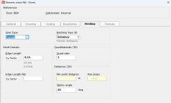
You can also re-mesh in AKABAK on a component/element level. I've attached a few pics showing where to set re-mesh and what it looked like before and after a driver surface was re-meshed. BTW, this feature has improved a lot when compared to earlier AKABAK (ABEC3) versions.
Attachments


- Home
- Design & Build
- Software Tools
- AKABAK 3