Greetings -
I'm in the process of pulling together the final parts for my pending AJ build. So grateful for this forum!! At the moment, I'm designing the chassis/heatsink and have been scouring the archives - most questions have been answered, however, it doesn't seem like anyone's tried the approach that I'm considering for this amp - I'd really value thoughts/caveats on the operating risks/considerations with the approach (don't worry about the cost of this - that's my call 🙂
Specifically, I'm considering using a Thermalright HR22 for each MOSFET to provide cooling - the clocking reviews say this will dissipate 130W without a fan - which I believe should give me >2x thermal headroom.
I also anticipate I'll need a jumper from the board to the MOSFET in order to work the spacing in the chassis; any troubles/caveats with that approach? (I believe I've seen it done on other designs with no concerns)
Thanks, guys - really appreciate your input/steer. Again, I know this is a costly way to work the cooling - I'm not concerned about that as much as working the aesthetics - of course, all secondary to getting the operating sound to be the best it can be!
Lee
I'm in the process of pulling together the final parts for my pending AJ build. So grateful for this forum!! At the moment, I'm designing the chassis/heatsink and have been scouring the archives - most questions have been answered, however, it doesn't seem like anyone's tried the approach that I'm considering for this amp - I'd really value thoughts/caveats on the operating risks/considerations with the approach (don't worry about the cost of this - that's my call 🙂
Specifically, I'm considering using a Thermalright HR22 for each MOSFET to provide cooling - the clocking reviews say this will dissipate 130W without a fan - which I believe should give me >2x thermal headroom.
An externally hosted image should be here but it was not working when we last tested it.
I also anticipate I'll need a jumper from the board to the MOSFET in order to work the spacing in the chassis; any troubles/caveats with that approach? (I believe I've seen it done on other designs with no concerns)
Thanks, guys - really appreciate your input/steer. Again, I know this is a costly way to work the cooling - I'm not concerned about that as much as working the aesthetics - of course, all secondary to getting the operating sound to be the best it can be!
Lee
Is there a Mouser B.O.M. available for the Universal PSU V3 (P-PSU-1V30)?
I would appreciate this very much!
Have a great day🙂
I would appreciate this very much!
Have a great day🙂
Greetings -
Thanks, guys - really appreciate your input/steer. Again, I know this is a costly way to work the cooling - I'm not concerned about that as much as working the aesthetics - of course, all secondary to getting the operating sound to be the best it can be!
Lee
At least one other diy'er has used the CPU heatpipes, his pics can be seen in the 'post your Pass pics' from maybe a year ago or there about. It looked like an air cooled engine. Pretty cool, actually. I've thought about this approach and it seemed doable so long as the sinks were surplus or really cheap off epay in quantity.. To some folks the aesthetic is as much fun as the circuit, so I say go for it. But I'd also under-rate any spec'd wattage within this application just as a precaution. in other words, one max two fets per sink depending on size. It seems like is there a lot of experimentation needed with this type of cooling before you commit to some fab'd out aluminum chassis bits to accompany it all..
Last edited:
I think this is what you are referring to. Check out Pass Labs Picture thread #2964. Built by JDG123. Real great looking F4, I have also considered this method but would need to find the heatsinks nice and cheap.
Good luck and don't forget to post lots of pics!
Mark
Good luck and don't forget to post lots of pics!
Mark
I could add that if I were to try it again attaching Mosfets directly to the heat pipes would be much better ;-)
6L6, thanks for your reply but I think I'm good now...
I do have another question:
I do have an understanding the way heat sinks are designed to work, convection. Being that heat rises up through the length of the fins and is in turn replaced by cooler air currents resulting in continuous circulation... What I'm not sure of is, will the heat sink I have be sufficient in cooling the transistors if they were situated in a horizontal placement?
The heat sinks measure 8.25" in width, 12" in height. The fins are 1" tall and consist of 26 fins across the 8.25" width with a 3/8" base.
The Aleph J boards fit nicely if I use the heat sinks horizontally. Is this alright, would you do this?
Hi Nelsondog,
I'm not 6L6, but I have been doing a lot of studying on the topic.
I think it would be far better to cut you heatsinks in half to a 6 inch height and use them with two fets per heatsink half. So they would be 16.5 wide and 6 in tall per side after cutting. Mount the Fets about 30-40% up from the bottom with the boards centered on the 16.5 width. Cut and mounted this way your heatsinks would probably work OK.
I don't think the horizontal fins would work out, but you could always mount them that way as a test before you build the rest of the chassis.
In general for non forced air applications, vertically orientated fins are much more efficient than horizontal oriented fins, and wide heatsinks are more efficient than tall heatsinks with the same total area.
Good luck.
Mark
I am 6L6 and would have to agree 100% with what rx7mark says. 🙂
That's probably enough heatsink for an AlephJ (which do run quite hot), but only if the fins are pointing the proper way.
Thinking about your amp, those heatsink dimensions wouldn't look bad if the fins were pointing up... Put the transformer on the bottom, attach the PSU stuff to the back, and have at it. 😀
Good thing I have some heat sink material left over. I'll cut a couple more pieces and extend the width toward the back. meaning, I'll leave the height and add to the width. I still think the more surface area the better in the proper orientation of course.
I guess I was looking for an easy way out. Thanks for your advice, both of you!
I guess I was looking for an easy way out. Thanks for your advice, both of you!
Hi all,
I've inherited an Aleph J with a misbehaving channel. I'm totally new to this whole build-better-stuff-than-you-can-buy thing, but I'm pretty excited to hear the results, and I hope some folks smarter than I will lend their expertise.
Here's what I have so far.
The previous owner didn't heed Egon's advice, and mixed up V+ and V-. It was bad. He replaced the output FET's to no avail, and decided to give the project to me as a christmas present. Thanks dad. So Q5,6,7,and 8 are new.
When I got to monkeying with it, I got a nasty buzz out of the bad channel. Closer inspection of the pcb revealed some scorching around Q4. I've replaced that, and the buzz is gone, but now I get a solid 28V across the output terminals. I didn't think to check the voltage across the terminals before changing the transistor.
Each channel is independently powered, and this one's PS is running +- 28.6V. I haven't figured out yet how to bring that down to 24V (did I mention I'm a NOOB?) but that's where that number's coming from, I think.
Some things that might help:
I get 9.4V across R8
I get 0V across R7
I get 0V across Q5->R16
Any thoughts on likely culprits? Should I replace Q3 and Q2 for good measure? Should I be looking for a smoked passive? Any guidance will be well received and most appreciated.
-Graham
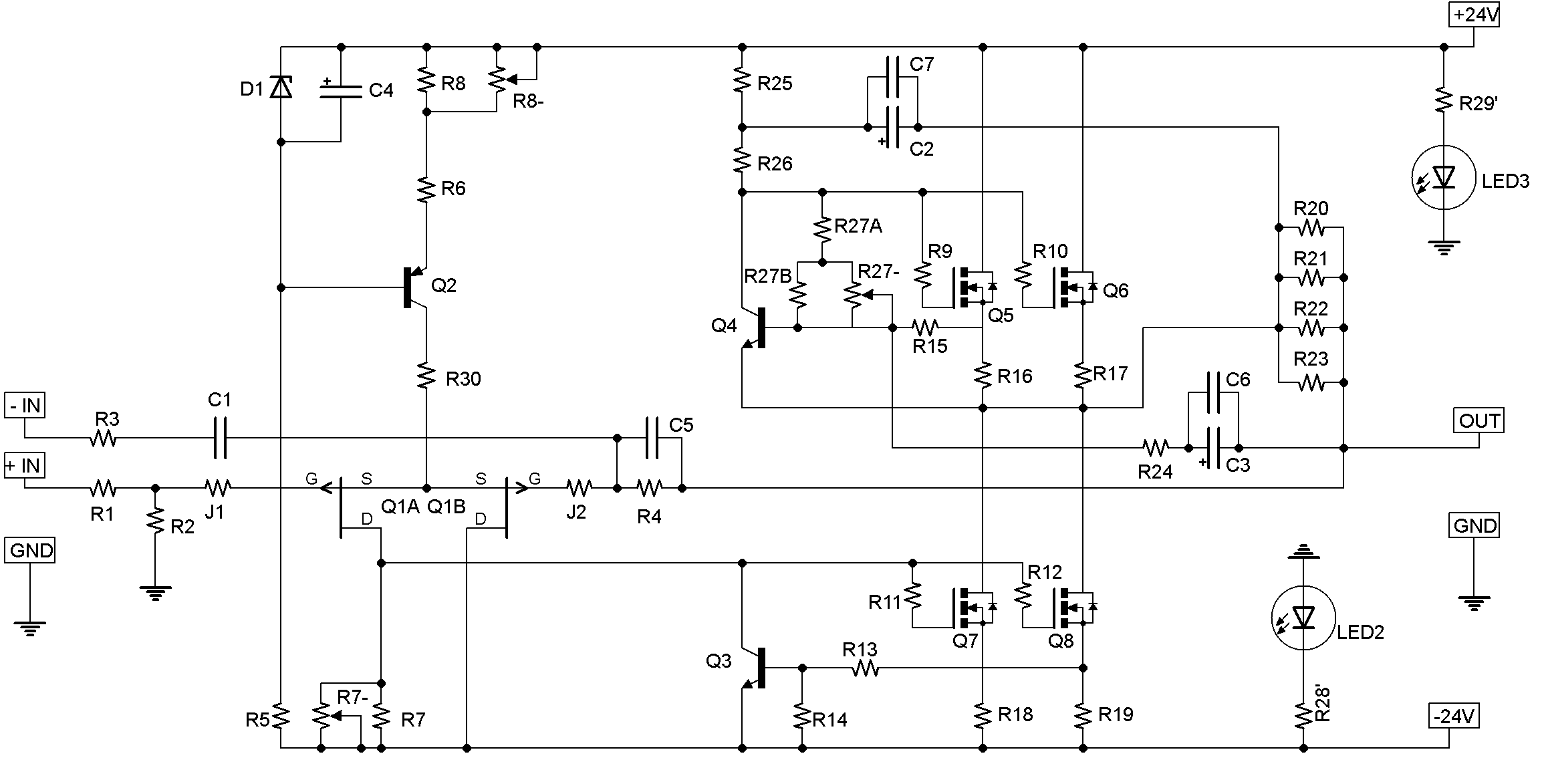
Hmmm...unless R7 is a pot turned all the way down then 0V across it means
there is no current flowing through Q1a. (I'm referencing the schematics here:
http://www.diyaudio.com/forums/atta...eph-j-universal-mounting-spec-aj-skema-bw.png
) You need about 4V across R7 for the output mosfets Q7, Q8 to turn on.
If R7 is a pot, does the voltage across it change when you turn it?
Dennis
Well, I've got the whole thing out of the chassis, and it turns out I do have 2.7v across R7. (I was tricky to get at in situ.) R7 is not a pot, but I've got several around and could swap one in to dial in 4V... Thoughts?
Thanks,
-Graham
Thanks,
-Graham
R7 looked suspicious, so I swapped it out. It's a 1k 1% part. V across R7 is now 1.7V. I have a pot at R27, but nowhere else. The schematic you linked to is slightly different to the one I've been working off of, specifically in that it calls for pots at R7 and R8. I just have 1k resistors in both locations.
My dad mentioned that once it's running, I should add pots to dial in 0.0v at the outputs, but we were doing so much other stuff at the time, that I didn't catch where they should go.
Also, thank you Dennis, for your help.
-Graham
My dad mentioned that once it's running, I should add pots to dial in 0.0v at the outputs, but we were doing so much other stuff at the time, that I didn't catch where they should go.
Also, thank you Dennis, for your help.
-Graham
I should also mention that with the R7 swap, R8 now has 8.3V across it, instead of the 9.4 it had...
- Home
- Amplifiers
- Pass Labs
- Aleph J illustrated build guide