Some quick thoughts:
A string link to the rear stub will work if a magnet is attached at the junction of the string and stub end and a curved ferric guide is placed just to the outside. It's a suggestion Frank Schroeder gave me earlier. He also suggested a low CG weighted arm with two cup and point bearings. I think the geometry will work, but the guide length might be a problem for both ideas and the string might twang.
I'm fairly certain the stub will follow the arc because of the acute angle, not despite it, because the side forces on the stylus will pivot the stub to the outside and the guide will want to fall forward.
I think friction at the pivot will be the major hinderance to eccentricity accommodation. That and mass.
The only mechanism I've come up with is a vertical pivot for the stylus, main arm, and CW fixed to a sled with the stub at the rear, which rolls on a rail which is connected to the horizontal pivot. Six or eight bearings, high mass, and potential wayward forces. As I said before "the perfect frictionless pivoting sliding bearing."
This whole thing is sort of a mirror image of the Birch. Even the error amounts and the three nulls reflect the results JCarr posted for the stylus path back about #822.
"Halbach Tunnel." I had to look that one up. Very interesting. I'd love it if you could make that one happen. What a lot of marketing features if you decided to take it commercial.
Carlo, your #2 design, "the sliding pivot" geometry is similar to this arm:
Angling for 90° - tangential pivot tonearms #888.
Last edited:
Highly innovative 2wice,
If there is a box you are thinking several miles outside of it.
If I recall correctly a halbach array is used to increase the strength of a magnetic field. It does have the disadvantage of making the field "lumpy". There will be preferred resting places between two repulsive halbach arrays this might cause the carriage to want to jump from one to the next. I suspect that using a short set of arrays in the floating carriage opposing a standard array of magnets in the rail may provide smoother motion.
I believe Mr Earnshaw would not feel violated by your proposal.
One thing that I have noticed with all magnetic levitation toys and devices is that they tend to giggle about a lot. To minimize the amplitude of the giggle and to maintain accurate alignment the magnet gap would need to be kept as small as possible. Making the gap small will stiffen the magnetic field and may push the frequency of the giggle into the audio bandwidth. Some form of damping may be required. It may be possible to use magnetic damping utilising the same magnets as used for levitation. If all goes well this could definitely solve the linear bearing friction problem.
From my experience I have concluded that a good solid mechanical grounding between armtube and its supporting structure is one of the most important aspects for tonearm sound quality. By floating the arm you will have no mechanical grounding except that at the guide bearing at the rear of the carriage. Hopefully the contact at this point will prove adequate.
Niffy
Hi niffy
Halbach arrays are inherently lumpy, but has been solved some years ago by the linear motor designers. They figured by changeing the Halbach pitch between the two components the unequal magnetic fields will ride each other. This resulted in cogless motors. You'll find this in modern BLDC motors also.
Your suggestion will also work but I like the shorted rear of the Halbach that keeps stray fields contained. Some don't like fields and wires close.
Rigid mechanical magnetic field coupling is very possible, some designs have a problem because of it, there is no damping they have to use active electronics for damping.
Dtut, lots of experimental toying ahead and I'll try every angle for sure. I will play with the string also.
Incredible knowledge and technologies involved, to me completely unknown. I often do not feel up to this thread.
If I understand correctly, the 2wice arm description reminds me somehow a syrinx (even mine has obviously a constant shaft length) but with the elongation at the base instead that near the vertical pivot.
Here the guiding mechanism is a curved rail that does the work of my gadget (see the arc in my handmade simulation) however without a mechanical forward push, obtained in this case simply by the stylus drag. Hopefully with far less friction than mine (but, how many wheels has the carriage?)
The overshoot problem is controlled from the center of blue circle: what I noticed was that maybe is not the best position (though geometrically perfect). Using a string you are pulling in the same direction of the movement you would like to brake, using a rod pushing outside, bringing more friction on sliding carriage.
Just one last thought. If the advance comes from arm rotation, errors will be of over-underhang (a few millimeters is not tragic), but if the rotation comes from the forward movement the errors will be of stylus positioning in the groove (a few microns and you're out: how must be precise the guide? and on eccentricity?)
That's why I did the syrinx guide that strange way
carlo
Doug - that's why I said that this solution tends to the Birch, and that the smarter solution seems your+schroeder magnetic guide
Dd - The graph is exactly that of 2wice, sustracting all those beautiful lines. The reason why the number 2 does not seem to me a Thales is that the pivot, approaching the spindle, generates infinite smaller thales circles (red dotted ones)
Ps: very difficult to explain such things not in my language, sorry
Attachments
From my experience I have concluded that a good solid mechanical grounding between armtube and its supporting structure is one of the most important aspects for tonearm sound quality. By floating the arm you will have no mechanical grounding except that at the guide bearing at the rear of the carriage. Hopefully the contact at this point will prove adequate.
Niffy
Seems to be possible to substitute mechanical grounding with massive tonearm part near horizontal bearings, center of mass located in the middle between two? Kind of inertia working against vibrations?
Niffy
Seems to be possible to substitute mechanical grounding with massive tonearm part near horizontal bearings, center of mass located in the middle between two? Kind of inertia working against vibrations?
Hi Walterwalter,
A large damped mass is a good thing to use as a mechanical ground, often better than the real ground as the real ground can be a source of vibration. What is useful is a pathway away from the cartridge for compression waves to escape via. Care has to be taken if any additional mass is added to any moving part of the arm as this will effect effective mass. It will also load the bearings that are supporting it and increase their friction, assuming they're mechanical bearings.
With the only contact point being at the rear of the main armtube which is then supported on the lateral bearing there isn't a direct path to ground. It might be a minor problem (and a bit off topic) but in my experience a short direct path to a ground make a big difference.
Niffy


Now that I'm looking at it again that rear linkage might not look so out of place. And it would simplify things considerably.
2wice,
Very nice! However, how to implement is the most important part. Middle slide part is a perfect application for air bearing, but once air bearing used, it will deviate whole purpose of pivot tangential arm. Four small v groove needle bearings as Niffy's may work, too.
Very nice! However, how to implement is the most important part. Middle slide part is a perfect application for air bearing, but once air bearing used, it will deviate whole purpose of pivot tangential arm. Four small v groove needle bearings as Niffy's may work, too.
Last edited:
If halbach tunnel works, I think it is perfect for a linear tracking arm. Sorry, I mentioned linear tracking arm.😀

Beautiful renderings 2wice, true hy tech arm: they say, a picture's worth ..
Finally I understand (hoping to) that the horizontal pivot is fixed on plinth, while the arm (and its vertical pivot) travels on the linear guide: this reassures me a lot for my Syrinx, because it is just what it does too (but with a linear old timer bearing).
What I still do not understand is if it is moved only by the stylus drag, and how is guided: from rear (tangent circle center) or in front (Thales circle center)
Congratulations - Carlo
Those Halbach bearings are in production or you'll build yourself? I've seen on wiki, really complex
If magnets are to be avoided. I think this will work.
It would require two channels, with matching channels beneath, for stability. Three round rods all touching side by side would create two channels. Use two balls in one and one in the other. From my experiments I found that the hardness of all parts is paramount. For the lowest possible friction tungsten carbide rods and sapphire balls. You might find that you have to reposition the balls every now and again but this would be no real hardship. This setup would give excellent mechanical grounding so may well sound better than the magnetic levitation design.
Niffy
Thanks niffy.
logically Solid contacts and simple things work efficiently.
This is just mental exercise. 🙂 I am working around a design if two ball bearings, one linear and one on the arch groove can work or not. Will be more simple/stable and less linkages would be better I suppose.
Regards
logically Solid contacts and simple things work efficiently.
This is just mental exercise. 🙂 I am working around a design if two ball bearings, one linear and one on the arch groove can work or not. Will be more simple/stable and less linkages would be better I suppose.
Regards
Hi Carlo
Would be a custom bearing build.
It is driven like any pivoting tonearm, rotation + drag force as a bonus, might have to counter the drag force a bit and I have an idea but cannot model it yet.
The 3 coincidence points on tonearm line between groove position, pivot and rear guide hopefully keeps everything in position.
I do like the rod and ball mechanism also, and it will enable a cheap check on the geometry.
I've rendered something like that also.If halbach tunnel works, I think it is perfect for a linear tracking arm. Sorry, I mentioned linear tracking arm.😀
It would work well I think.
If magnets are to be avoided. I think this will work.
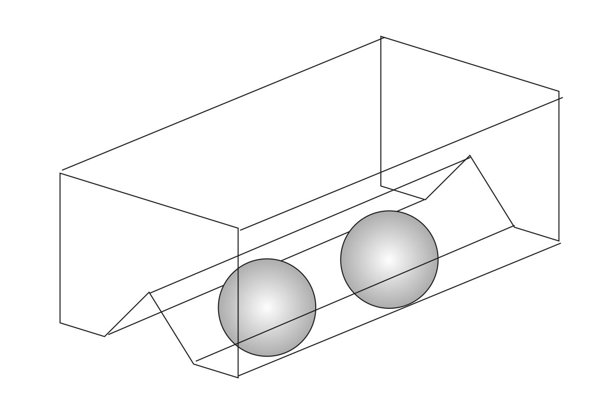
It reminds me of this tonearm in another thread. I think this approach can be used in the carriage. Similar to Niffy's idea but using 4 rods side by side to make 3 channels and use 3 balls, 2 in front 1 in back (vice versa), and you have a low friction steady rolling platform for the vertical arm to sit in the middle of the triangle, preferably with 2 spikes on 2 dimples. One spike is cone shaped set screw to adjust azimuth. Low friction and mechanically grounded with no chatter. The optimum placement of the 3 balls takes some experimenting though.
If halbach tunnel works, I think it is perfect for a linear tracking arm. Sorry, I mentioned linear tracking arm.😀
If I'm a bouncer, you'd get kicked out of the club! Just kidding! Haha...
In a parallel tracker, a magnetic channel like that would have low friction but I think you would have to make the vertical arm long enough so the cartridge is not affected by the magnetic field. Your airbearing arm has an extremely short length which probably can't be duplicated on a magnetic track. Perhaps one can make an effective shield around the tunnel.
Oops, I just talked about airbearing! 😱 😀
- Home
- Source & Line
- Analogue Source
- Angling for 90° - tangential pivot tonearms