Yes I found examples of 6x6 matrix used for 3d models. It’s the inverse of the compliance matrix, according to one answered question on the forum. Compliance matrix entries have inverted E1 etc elements, so it’s not surprising the the inverted matrix has elements with the same order of magnitude as E1 etc.Just found the example below of anisotropic material.
But for 2d model I need a 4x4 matrix.
I may move to shell solver which I think uses a 6x6, and has more capabilities I think and may be more accurate. No answer yet on the Elmer forum.
Last edited:
But for 6x6 we would need values for E3 and a bunch more poisson ratios. Hard to believe that people measure all of this, there are probably ways to estimate/fudge it for 6x6.
Paul,
I think it's only two more poisson ratios (due to the symmetry thing), and I doubt our plate problem will be sensitive to the properties we have to guess at. But I also suspect it would be best to get the 2d model to work. At least it seems that would be a lot less computation intensive, right?
Eric
Yes that's what I thought. But the plate solver seems to be little used (eg in the GUI, I had to manually add it as an option). And while I have viscous damping working in the plate solver, it looks like Rayleigh damping is not available.it would be best to get the 2d model to work
Shell solver should also allow us to look at (eg) curved plates or cylinders & (I think) prestressed plates, which may be advantageous due to multiple wave types & mode conversions giving higher modal density, and possibly good dispersion properties. So I may give it a try.
I expect it will be slower, but it's not full 3D, it's a 2D surface in 3D space, so I would presume its still a lot faster than a full 3D model...
I did a run of the shell solver in Elmer, with some help from the Elmer forum. Seems quite fast.
I used the parameters that Eric specified for the various methods we are using.
This is with a ~20mm irregular quad grid.
6.569631727384E+001 8.103597970099E+001 1.067250788729E+002 1.428682047754E+002 1.896106959322E+002 2.471242652303E+002 2.493290069537E+002 2.646124709696E+002 2.901706906275E+002 3.155420445030E+002 3.261398544208E+002 3.726718976647E+002 3.951165178921E+002 4.298985583613E+002 4.862093041516E+002 4.981014295635E+002 5.615367244804E+002 5.767764269576E+002 5.774176005018E+002 5.885749716995E+002 6.022143062215E+002 6.381162635390E+002 6.682300768702E+002 6.845523880456E+002 7.037661538244E+002 7.414167115700E+002 7.703336154684E+002 8.093355672665E+002 8.306518070135E+002 8.852309043771E+002 8.881928050177E+002 9.716035779981E+002 9.789938996793E+002 1.011465363737E+003 1.012515662659E+003 1.027269844997E+003
I also found a reference about orthotropic materials that covers both the compliance matrix and its inverse, the stiffness matrix.
http://homes.civil.aau.dk/lda/Continuum/material.pdf
Coordinates are radial, longitudinal, and tangential, which apparently come from slices through timber logs.
Paul,
I'm a little confused about your different options in Elmer. This time, you used the "Shell Solver". Wasn't what you were doing previously also using the a shell solver? What's different? Oh, wait, it's the "irregular quad grid" elements, instead of triangles. Is that it?
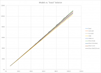
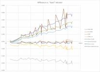
I've added your newest data to our charts. In the first chart, it's getting hard to distinguish the lines from each other, but the new data is the bumpiest. In the second chart (diff vs, exact), the new result has the most variable difference vs. the exact. The modes with the greatest difference vs the exact are the high order 1,N modes.
Maybe try the quad elements at 5 mm? How many nodes are there in a quad element? The LISA elements have 8. The corners and the midpoints of each side.
Eric


Hi Eric
Previous runs in Elmer were with the Smitc Elastic Plate solver, which is a dedicated solver for flat 2D plates. Now I am looking at the more general shell solver which is basically a 2D manifold in 3D space, so you could do cylinders or ship hulls or whatever. But it also has other features like Rayleigh damping, a 6x6 matrix for ortho which we have some info on, and I think better options for output of velocity
It certainly looks rough! I tried a second order element yesterday, but it didn’t accept it. Another thing I could try is regular shaped elements which is harder to do I think in gmsh. The quads I used here are from recombination of triangles, so you end up with a random pattern. More research 🫤 Maybe the convergence tolerance is too small. There are like 1000 settings to fiddle with.
Could it be picking up another series of in-plate modes? There does not seem to be more data points in this series, so I guess not. Or it could it be that this is closer already to the truth than the others. How would we even know? Shell models are more general again than Reissner Mindlin.
That seems to be a problem with a lot of the research in this area. You see lot of papers that never leave the realm of computation. Very few check results against measurements (which have their own set of complications). Where is the ground truth?
Last edited:
Probably none of this matters much anyhow, because what I am aiming for primarily is analysis of the response below say 500 Hz. That’s where we stand to make improvements with fem I think. The mid range takes care of itself in DML, and the highs are a different problem altogether. I doubt the errors at this level will make much difference.
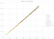
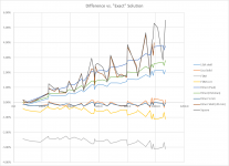
Would you mind adding this to your graph Eric? This is with structured (square) mesh, and all convergence tolerances set to 10^-11. Values do look smaller maybe on the other side now 🙂
6.573769554046E+001 8.106250951077E+001 1.067267229449E+002 1.428456374177E+002 1.895509826913E+002 2.470067472737E+002 2.500544782016E+002 2.652646957200E+002 2.907047580284E+002 3.154165111593E+002 3.264957870403E+002 3.727912370542E+002 3.950260387884E+002 4.297742926895E+002 4.861246726247E+002 4.976598370793E+002 5.654410298504E+002 5.766982302128E+002 5.805009210716E+002 5.890467629829E+002 6.056749807722E+002 6.410717244469E+002 6.671791603213E+002 6.868387120519E+002 7.041734291522E+002 7.431604869091E+002 7.694350229975E+002 8.102577963002E+002 8.319346898473E+002 8.838438909093E+002 8.883881609738E+002 9.728119528195E+002 9.778475123692E+002 1.010832299952E+003 1.024748540320E+003 1.039600149946E+003 1.064419837402E+003 1.078972529117E+003 1.099307577026E+003 1.127340855617E+003 1.144402483705E+003 1.150878057874E+003 1.192143409038E+003 1.199882414180E+003 1.265963880625E+003 1.296114427491E+003 1.304513197999E+003 1.317786850377E+003 1.342902490150E+003 1.430993900827E+003 1.456379224577E+003 1.472327214577E+003 1.479786621351E+003 1.530575343478E+003
Paul
Thanks Eric
I may try one more run with a finer mesh, before I return to the smitc plate solver. There is also something you are meant to define called the 'director' for the shell solver, which seems to be the normal to the surface at each node. Dont know if its important for such a simple geometry though.
But I have some bad news I found out last night by looking at the plate code, and confirmed definitively on the Elmer forum upon the return of one of the developers to the forum. Neither the plate solver not the shell solver supports orthotropic. Sheesh. 😱
Paul,Neither the plate solver not the shell solver supports orthotropic.
Oh, that is discouraging.
Eric
+ @pwayPaul,
Oh, that is discouraging.
Eric
Yes, not good news. I don't know for you, but for me the simulation approach is clearly a highly challenging way by the DML itself (its behavior, its components), the mix of different domains (electricity, mechanics, acoustics...), the simulation tools. Many things to learn. The good point is we are approching the topic by different ways. In my "requirement list" to a simulation tool, I have reduced the priority for orthotropic material and increase the one on the additional components on the plate like the surrounding and the exciter (local mass and stiffness). I should be able to implement in the next days additional mass and stiffness in the FDM script.
The step after might be to add free edge conditions but here, I don't have the structure for orthotropic material (prepared for the current script but not tested). For the suspension, not clear for me how to model it. Is the simple approach of spring and damping enough?
Christian
PS : does all of that mean for FEM tool we should have a new look to the free software offer?
Hi Christian
Im not using ortho at the moment, but I was interested to do a similar run where the angle of the plywood panel was moved in relation to the frame, with a belief that this would improve the eigenmode distribution as did a slanted side for isotropic.
Also in the back of my mind is the idea that we may be able strip out most of Elmer leaving just the bits for panel simulation, then package it with py2exe or pyinstaller as an easy-to-use set of tools for DML design, with a simple user interface (maybe just command line or menu driven). So I wanted to investigate the most general model available.
Paul
I plotted some graphs myself comparing plate (smitc) solver with the shell solver at different mesh resolutions, using a regular grid.
I found that plate and shell performed similarly (just from viewing the zoomed out graph), both at 20mm and 10mm resolution. The lines were over each other. Not sure why the shell solver seemed worse previously. In fact, at 20mm both are equally bumpy. I expected shell to be worse since I read that shell grids need to be finer, but maybe because they are normally in 3D.
In both cases, there was an almost identical improvement in the values for 10mm grid. I have only showed results for shell below but plate solver looks the same. You can run the other cases with python. I guess you would get diminishing returns from 10mm down. Interesting that both methods suffer similar errors.
Interesting that except for the slope of the line, the closed-form solution is very accurate.
Code with data attached.
Last edited:
Paul,
Wait, if you do your own plotting, what am I going to do? Haha.
Can you share the data for the four new runs? I actually would like to add them to my own plot. What type of elements did you use for each?
I didn't see an attachment. If it's a python file I don't think I can open it, unless maybe it can be opened as a text file?
Eric
Wait, if you do your own plotting, what am I going to do? Haha.
Can you share the data for the four new runs? I actually would like to add them to my own plot. What type of elements did you use for each?
I didn't see an attachment. If it's a python file I don't think I can open it, unless maybe it can be opened as a text file?
That was one thing that I found interesting. Even Lisa and Elmer seemed to have errors that were similar, while the errors in the FDM were almost mirror images of the FEM errors.Interesting that both methods suffer similar errors.
Eric
Burntcoil is starting in earnest on his exciter build over on his thread.
https://www.diyaudio.com/community/threads/dml-exciter-design.393544/latest
https://www.diyaudio.com/community/threads/dml-exciter-design.393544/latest
What DSP do you guys use? From what Ive read, it seems the most versatile could be to buy one of the recent Pioneer or Onkyo home theatre systems with Dirac live, or Denon system with latest Audyssey app configurable from laptop. Lots of channels for crossovers or multipanel systems, plus subwoofer channel(s). Another option may be to put all music on a laptop and use a streaming software plus windows Equaliser APO, again feeding a multichannel home theatre system.
I doubt it's worthwhile going to true 'hifi' amplifiers as to get a system with multichannel and DSP would be very expensive, and I doubt that differences in distortion figures can be heard anyway. Noise may be an issue though in sub-hifi systems. And possibly power, as the way they quote power handling in the multi-channel systems is pretty bogus.
This thread on diyaudio is very interesting.
https://www.diyaudio.com/community/...controlled-integrated-dsp-amp-tas3251.325826/
They built a modular system that maintains a digital signal path (no multiple ADC/DAC as with eg the miniDSP) with one of the latest TI class D amplifier chips TAS3251. They adopted the design from the TI evaluation board for that amp, (which has been withdrawn from sale). But Im not sure I want to commit to that sort of effort/risk, which required soldering SMD by hand. Also the chips have very long lead times now, but it looks like a great solution. But if there was a bunch of people starting on the same project, I would be interested...
Paul
No DSP here, still in the wish list. I had a look to the possibilities around Raspberry Pi with linux with Camilla for example but not go very far. For now I haven't found a solution with the effort (time), cost, performance I search. I am not in the idea to sold SMD... I make some modifications of TP3116 PCB, that's my limit : some passive components to remove on a cheap card.What DSP do you guys use?
Christian
- Home
- Loudspeakers
- Full Range
- Application of Impulse Excitation for DML Design and Analysis

