Plutot: tout ces froufrous sont fait pour s empiler et coutent cher. C est le but. Seul un leggins dit toute la vérité.
Maintenant faut le traduire en anglais.
Better an Allo Station ???
Maintenant faut le traduire en anglais.
Better an Allo Station ???
Women living in Sauna are the best dressed in winter (sorta of cultural translation just for you)Incomprehensible...
//
Here the english translation : all this stacking boards are just a modular plan to undress your wallet. Soon this antena will need a special Fifo Numetal casing option and so on... It is like a mortgage if you prefer.
 @funhouse61 Your translations are not working. Please fix however you are using the translation and post in English only.
Merci.
Always more stacks option like BMW...
What is a fifopima without memory and why the more expensive should have more fifo memory...is that needed or not, is that so expensive to be an option or is it for different uses ? Gogo trap ?
What is a fifopima without memory and why the more expensive should have more fifo memory...is that needed or not, is that so expensive to be an option or is it for different uses ? Gogo trap ?
Amazing how Ian keeps innovating. This is going to be sixth generation of his FIFO products I’m integrating.
If I had to guess, the FIFO Q7 is going to be an end game solution for R2R-DACs, but I’ll wait for the documentation…
Iggy, why the ‘tude, dude? You might allow that there is more to digital audio than caps and resistors, and if you read the docs you will certainly find a level of excellence in concept and execution that finds no analogy in car trim or sartorial excess…
Oh I am a customer and gave gen 2 and first fifopi gears. But too much stacks that deserve to be in a standalone pcb at a more fair price imo.
The design is wasted because it must stay squared pcb size that stack on a Pi, despite there are still uf-l pads. Hence my post above. It is a perfect modular thing where you need several lego to make what should be on a standalone with the price divided by the number of the stacked pcbs with loosy connectors in the RF domain. As the numerous power supply banks as expensive than a small TV but that non bring a real advantage but the concept of DC...blah. Perhaps better not to have a stacked antenna and a little more room and also better quality parts than those x7r caps everywhere as better parts are avialable now and that is diy afterall and non commercial forum and a brand now as Ian is selling with distributors as well. Same occurs for several threads imho.
Not all is bad, but at the end the thread should be in the commercial area. There are also some alternative like thewellaudio from a baned member that make as good products if not better because still sound quality in mind despite the ambition is certainly the same behind.
The thing that upset me is it seems designed as commercials options like a BMW. Analogy is valid imo.
Dose FIFOMa work well with r2r DAC?If I had to guess, the FIFO Q7 is going to be an end game solution for R2R-DACs, but I’ll wait for the documentation…
Nice looking project. Ian's modules are such a joy to work with. I'm getting ready to swap out my StationPi PCB for the new StationPi Pro (SPP) board - upgrading my V2 to V3 of what I call, the Ian DAC Stack!thanks to Doede and Ian
@Ian Just starting to retrofit my DAC Stack V2 with the new StationPi Pro (SPP) PCB. My previous build had the ConditionerPi face down under the RPi - and worked very well. With your new design and the daughter PCB attached, there is no physical way to install the ConditionerPi to the daughter PCB due to the 3 capacitors. It seems it might be possible to mount the ConPi by using a DIP extender/riser (below) to give more clearance for the ConPi.? If I were to pursue this approach would the ConPi still work as expected with the RPi, or is there new circuitry integrated into the SPP, or daughter board that would interfere? Or, is the ConPi still needed with the new SPP PCB at all? I know some things must be given up with a new design, so if it won't work that's an acceptable answer too. 🙂
Edit: What is the J10 header used for?
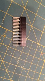
Edit: What is the J10 header used for?

Last edited:
Of course there are other issues/constraints to deal with that arrangement too. The standoff holes aren't aligned and it makes that part of the SPP much taller and may not fit in my original case(will not fit once the RPi is attached 🙁 ). I can shorten the extender to fit closer as well. The additional support needed I can deal with.
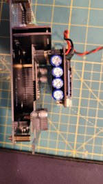
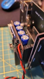


Do you have a part # for the extra long Flexible Ribbon cable for 4D display to the controller?thanks to Doede and Ian
I'm following your notes on setting up the 4D System screen using your code. I can get it to work fine on the development controller by by using the compile and download commands. However, whenever I disconnect the display and hook it to the StationPi Pro connector it reverts back to the 4D splash screen and not your large display buttons. Is your code 'flashed' to the screen or is in volatile memory? Is there a step I'm missing?
Edit: BTW, my rebuilt stacks on the new SPP board are working as they should - even though I haven't tested all inputs and options yet. Just doing an initial powerup and sound check now. Also, the ConditionerPi is working as expected with both it and the RPi mounted on the daughter board - similar to my original configuration.
Now all I need to do is get the 4D display working. 🙂
Last edited:
The Comp'nDownload appears to work ok, and I get no error messages (see below). I've tried a couple times now and the display never changes when hooked to the SPP. Is there a jumper I'm overlooking, or 'saving' of the your 4D code once it's downloaded to the display?
Just to be clear, either the 24PT, or the larger 28PT display can be used interchangeably? I've tried both, neither worked.
Anyone else running into this issue, or is it just me? Ideas?

Just to be clear, either the 24PT, or the larger 28PT display can be used interchangeably? I've tried both, neither worked.
Anyone else running into this issue, or is it just me? Ideas?

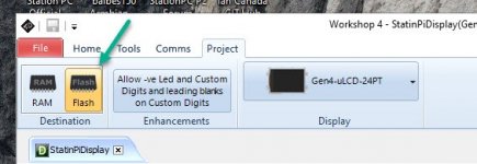
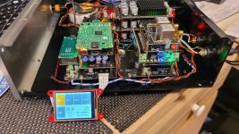
I guess I'm having a conversation with myself! 🙂 Anyway, it's funny how one small detail makes all the difference in something working or not. On the Project tab of the 4D IDE the destination must be set to Flash not RAM. I knew there must be someplace to perform the flash. Once I found it and changed it from the default of RAM, everything made sense and it worked. Touch screen works and I've got it displaying controller information too. Here's an image of my rebuilt-stack. I still need to bring a USB jack out to the back panel. Then I'll have all the inputs I use available. Of course, I have to mount the screen on the front panel as well and put the finishing touches on everything.


- Home
- Source & Line
- Digital Line Level
- Asynchronous I2S FIFO project, an ultimate weapon to fight the jitter