Whoops, I gave wrong info about condition of led. It was removing the first one I think I killed the legs removing it. After "repair" and R27 cooked again, LED is fine. So small cap is fine? I will carefully remove and measure in gizmo, assuming it measures caps.smd caps - hardly possible to be damaged
elco - only if LED didn't survive
Desolder station on porch this morning! Hope I don't get carried away? Main reason I won't let myself buy a sawsall....
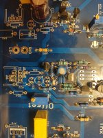
Hmmm, that cap on board is 100uF 25 volt. IIRC, schematic showed smaller value...is this not critical value? If not, what range will work, assuming correct size footprint? I may have something on hand....even if led ok, If I have it why not replace, etc.

Odd. So far, T6 good, T7 good, led good and C6 cap good....on tester gadget. I am still removing the resistors, but other than R24 everything looks fine. Did I kill an output?
What test next, or just reassemble and go again?
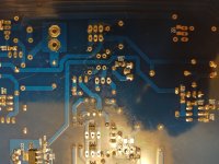
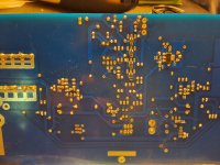
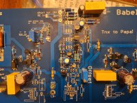
Here's pic of board with R21, R22, R24 T6, T7, C6, LED removed. Will remove other resistors....
What test next, or just reassemble and go again?
Here's pic of board with R21, R22, R24 T6, T7, C6, LED removed. Will remove other resistors....
Attachments
outputs are hardly killed, considering that there is 10A overcurrent protection
though you can remove output mosfets from pcb and try without them;
pucks you can test with famous multigizmo tester (which you have as far as I remmeber)
for said test, you need to establish proper DC NFB path for servo action, simply shorting zeners between output gates - ZD3 and ZD4
then you'll have proper DC offset at output to check and sine at output, even if without any power
enough to check with scope (?) or at least Vac meter, but strictly without load
Multimeters, but no scope. Not sure what is meant by "shorting zeners between output gates ZD3 and ZD4" "to establish proper DC NFB path for servo action," sorry, I'm a bit thick here....
I thought I would need to remove Zeners and put in tester, but if they can be measured in circuit, I would appreciate the schooling on exactly how done.
Is this basically what you had other member remove board from mosfets, short to complete circuit and so forth?
If so, I think I know what to do, maybe! 🧐
Russellc
Not sure what is meant
temporary put wire shorts in place of said zeners
or simply put wire- shorts in between gates and sources, in place of removed pucks
necessary for function of NFB in amp
How did you test these ZD 3 and ZD 4? In circuit, or removed?ZM, yes, that would be very helpful. Zd3+4 are good. Thx
Russellc
I think I see, the shorting between g and s where pucks normally are. Not g and s of zener, obviously!temporary put wire shorts in place of said zeners
or simply put wire- shorts in between gates and sources, in place of removed pucks
necessary for function of NFB in amp
I am going to replace parts, check in again with progress then short the Gs to Ss and try with measurements and check in.
At work now, once I get home. Hopefully that will uncover what is wrong, after I post measurement results...
As an aside, I got the dedolder station from Amazon. Inexpensive, works excellent, after suckering the pad from back of board, many parts just slid out! I have no idea how durable it is, but seems pretty solid...for price especially.
https://www.amazon.com/YIHUA-Desoldering-Variable-Temperature-Function/dp/B08BK69H2M
https://www.amazon.com/YIHUA-Desoldering-Variable-Temperature-Function/dp/B08BK69H2M
Not g and s of zener, obviously!
obviously
especially if zeners are having C and A, not G and S


All those are dealt with. Still puzzled that all removed parts test good. Makes me feel like something missed.
So, once parts back in and g to s shorts in place, will power up off the mosfets, and duplicate measurements from cwlo's tests.
I'm likely missing a lot, but gleen nothing from poking dead one with knowledge on hand! Will be measuring it once stuffed and g to s shorted.
So, once parts back in and g to s shorts in place, will power up off the mosfets, and duplicate measurements from cwlo's tests.
I'm likely missing a lot, but gleen nothing from poking dead one with knowledge on hand! Will be measuring it once stuffed and g to s shorted.
- Home
- Amplifiers
- Pass Labs
- Babelfish XA252 / Babelfish XA252 SIT / Babelfish XA252 SET