


Ditto!Thanks Nelson !!!
Which one are you going to start with Bob?
Ditto!
Which one are you going to start with Bob?
Well im surely not Bob, but thanks for asking 🙃
I am going to start with the Lamp Tokin AMP, but with resistor on heatsinks instead of the lamps, we have got 230V mains here in Sweden = No 300W 120V lamps to be found.
Should be a fun sonic compairson testbed between my beautiful twin 2SK182E versus my just as beautiful twin THF51 Tokins🥰
But them twin 100V powersupplys gonna cost me a pretty penny… 🙂
So, i am wondering: Do you HiFi building dudes think it is possible to later also use them 100V powersupply nuggets in the other Pass proposed SIT -topologys?
…With reasonable modifications possible to handle for a happy fairly n00b amp builder like me?🙃
Or is it simply not a good idea at all?
Yes, thank you for the PDF!
The 2nd last example in the PDF using P-channel mosfet as CCS but with a note that voltage could be "reversed" to have better noise rejection looks a bit like this one by Ben Mah?
https://www.diyaudio.com/community/...ommon-drain-mu-follower-amplifier-45w.371187/
I wonder if any PCB's was made?
Is there also a full schematic and tested version of the N-channel version (last schematic in PDF)?
I don't like to experiment too much......better having other doing the hard work")
Is it planned to have some PCBs at DIY Store for these designs or is the PDF what we get build like say a THF-51s amp from?
The 2nd last example in the PDF using P-channel mosfet as CCS but with a note that voltage could be "reversed" to have better noise rejection looks a bit like this one by Ben Mah?
https://www.diyaudio.com/community/...ommon-drain-mu-follower-amplifier-45w.371187/
I wonder if any PCB's was made?
Is there also a full schematic and tested version of the N-channel version (last schematic in PDF)?
I don't like to experiment too much......better having other doing the hard work
Is it planned to have some PCBs at DIY Store for these designs or is the PDF what we get build like say a THF-51s amp from?
most of them already covered on the list, though in usual ubercomplicated way
for more down on earth solutions, as you said, look at Ben's and other Greedy Boyz work
Yea, well but what would you generally say about going the 100V route in compairson to the 40- 60V propositions? Really not adviseable? Could be the really good earcandy?
Then it could be a "Lazy singing Bush"?
Do you like the sound of this amp with THF51s?
PCBs are available?
I posted that simply to point to practical "know-how"
For everything else, either ask in thread of interest, or use PM
Lets keep this thread clean
Yea, well but what would you generally say about going the 100V route in compairson to the 40- 60V propositions? Really not adviseable? Could be the really good earcandy?
besides starting contemplation - "is that amount of power, that amount of DF and that type of amp in general adequate for my needs" , there is simply no better way to choose an amp than by your mental picture of finished one
compare dissipation figures between various arrangements, note their resulting power, and translate dissipation figure in realm of kilos of Aluminum, VA in PSU and amount of miliFahrads
if your heart goes tickyticky just thinking of big Aluminum Cube or shining bulbs with smaller aluminum cube - go with 100V version
if not, choose some with Mu/CCS , and count that VA is almost halved
I wonder if I could scrounge up some outputs from this popular industrial application from my childhood...

Maybe if you were lucky enough to have this version.
Cheers
I bought 4 of the THF-51S parts when the whole "While They Last" thread was first started. Since my DIY skills more or less boil down to being able to solder and follow instructions, I don't really understand the circuits Nelson shared in the PDF. Specifically, can somebody tell me what the things I've noted in these JPEGs taken from the presentation mean? And I for one would be REALLY appreciative if one of the more accomplished members of the forum would actually share a complete circuit, with part specifications, that would make use of the THF-51S parts.
Attachments
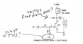
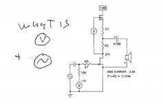
For starters all voltages are referenced to ground, that triangle of parallel lines.
V is a voltage source. Could be anything, including battery, solar cell,or a circuit detailed later in the piece.
The S laying on its side represents signal - a crude picture of a sine wave.
Basically, as simple as this circuit is, it works. Later in the piece some details are fleshed out a bit more.
The friendly people in this forum will be happy to answer additional questions, and the process will also help those who are more shy.
For that you deserve thanks.
PaulInWA, Zen Mod's Singing Bush amplifier is based on the concept shown in the second schematic.
Singing Bush
In the first schematic, the light bulb drops voltage as it heats up. The -3V is to be provided by a negative voltage supply which is applied to the gate of the SIT to adjust and control the current through the SIT. Michael Rothacher's L'Amp is an example of this concept.
Michael Rothacher L'Amp
diyAudio L'Amp Thread
Last edited:
Nelson, Thanks for explaining those symbols. Obvious except when you don't know what they mean LOL.PaulInWA, Zen Mod's Singing Bush amplifier is based on the concept shown in the second schematic.
Singing Bush
In the first schematic, the light bulb drops voltage as it heats up. The -3V is to be provided by a negative voltage supply which is applied to the gate of the SIT to adjust and control the current through the SIT. Michael Rothacher's L'Amp is an example of this concept.
Michael Rothacher L'Amp
diyAudio L'Amp Thread
Ben, I appreciate the references/links to Singing Bush and L'Amp. Looking at those sources gives me more context to understand, and possibly build, the circuit. For some reason those links didn't appear until I went to reply to your message and they showed up in the quoted text. That seems weird and unclear to me if that is just a quirk of my browser or ...?
new board is acting that way - links are in bluish color (normal text black) , and blinking when you hover your mouse over
if you have some color setting preventing visibility of that, change color scheme in browser
or just stay blessed in ignorance, as I am ...... chillin' all day long

if you have some color setting preventing visibility of that, change color scheme in browser
or just stay blessed in ignorance, as I am ...... chillin' all day long


- Home
- Amplifiers
- Pass Labs
- BAF 2022 SIT AMPS