Regarding the negative voltage on the gate (-3V), it is absolutely necessary to control this voltage when playing with normally-on devices or else maximum demolishing current will flow.I bought 4 of the THF-51S parts when the whole "While They Last" thread was first started. Since my DIY skills more or less boil down to being able to solder and follow instructions, I don't really understand the circuits Nelson shared in the PDF. Specifically, can somebody tell me what the things I've noted in these JPEGs taken from the presentation mean? And I for one would be REALLY appreciative if one of the more accomplished members of the forum would actually share a complete circuit, with part specifications, that would make use of the THF-51S parts.
@Nelson Pass, @Zen Mod, @6L6, @Michael Rothacher: Is there is any significant sonic signature difference of these new topologies with THF-51S compare to Sony VFET from the lottery? (Just trying to prioritize projects ") ) Thanks you.
) Thanks you.
) Thanks you.
Last edited:
A single 300VA toroid like the AN-3236 has a pair of secondaries that output 36VAC each. With each secondary across it's own bridge rectifier and linear filtration you will get ~48VDC, which is a little high for the +40V circuits shown and too low for the +60V circuits, but might work, just at a different operating point that isn't quite in the sweet spot. If you instead wire those secondaries in series, dot-to-no-dot, and put it across a single bridge rectifier, that 72VAC should give +96VDC rectified. Pretty close to 100V.So, i am wondering: Do you HiFi building dudes think it is possible to later also use them 100V powersupply nuggets in the other Pass proposed SIT -topologys?
…With reasonable modifications possible to handle for a happy fairly n00b amp builder like me?🙃
Or is it simply not a good idea at all?
If you think you can get these designs to work reasonably well with 48V or 96V then you can do that with a single trafo.
Would something like the Super Regulator board in the store be what you could use to provide and "control" the -3V on the gate? I don't suppose you could just stick a battery there for breadboarding the circuit? https://diyaudiostore.com/collections/power-supplies-accessories/products/super-regulatorRegarding the negative voltage on the gate (-3V), it is absolutely necessary to control this voltage when playing with normally-on devices or else maximum demolishing current will flow.
You could use a super regulator but it is over-kill. A trim pot/voltage divider is also needed to adjust the voltage as the -3V shown in the concept schematic is an example only, as the voltage needed will depend on each individual SIT.
A simple regulated supply as shown in Michael Rothacher's L'Amp will suffice:

A simple regulated supply as shown in Michael Rothacher's L'Amp will suffice:

Thanks. Continuing the trend of just how stupid a question can I figure out to ask, looking at that circuit and reading some of the source material I'm guessing that Michael's choice of a transformer with 40VAC outputs gives you something like 55 VDC after rectification. The circuit Nelson suggested had 100 VDC to a single 300 W light bulb that I think drops the voltage to 18VDC. Michael's circuit seems to use two 300 W bulbs in parallel with ~55 VDC input. Does that also drop the voltage to ~18VDC? A voltage drop calculator I referenced seemed to suggest that, but I was just guessing at the resistance and current draw part of the calculator (https://elecurls.tripod.com/drop-res.htm). But it also seems like different requirements of the 2SK82 versus the THF-51S I would use might account for the difference in design?You could use a super regulator but it is over-kill. A trim pot/voltage divider is also needed to adjust the voltage as the -3V shown in the concept schematic is an example only, as the voltage needed will depend on each individual SIT.
A simple regulated supply as shown in Michael Rothacher's L'Amp will suffice:
View attachment 1102585
Yes, different load lines for 2SK82 and THf-51S chosen by Michael and Nelson.
Some information on load lines (tubes shown but applies to SITs also):
Load Lines
Some information on load lines (tubes shown but applies to SITs also):
Load Lines
This one helped me out a lot
Here's a trash heat sink idea, a CPU cooler bolted to a THF-51S. there's a smol TO-3 mica and goop in between that's hard to see. I don't know what brand/model these CPU coolers are, these were gifted to me by a friend. Eventually I'll try to build an amp with these, but it could be a while.
Attachments
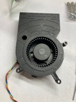
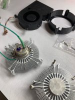
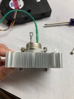
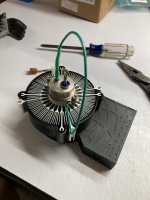
Gpu... grafic card maybe https://www.amazon.it/BAZA1233R2U-chassis-integrated-machine-cooling/dp/B0927CG3VYHere's a trash heat sink idea, a CPU cooler bolted to a THF-51S. there's a smol TO-3 mica and goop in between that's hard to see. I don't know what brand/model these CPU coolers are, these were gifted to me by a friend. Eventually I'll try to build an amp with these, but it could be a while.
This is a great idea and allowed these coolers to have a second life !Here's a trash heat sink idea, a CPU cooler bolted to a THF-51S. there's a smol TO-3 mica and goop in between that's hard to see. I don't know what brand/model these CPU coolers are, these were gifted to me by a friend. Eventually I'll try to build an amp with these, but it could be a while.
- Home
- Amplifiers
- Pass Labs
- BAF 2022 SIT AMPS