All I can really add to this is: It's too easy to second-guess yourself in the world of electronics design and especially troubleshooting. Keep trying different perspectives, keep a fresh mind (sleep well and go at it the next day if you need to), and best of all, be completely open to the fact that anything you hold as gospel might fall apart before you reach a useful conclusion!
I try and ask myself: What, in this system, affects the results I'm getting? (This includes my observations because the observer is inextricably bound to the system under observation and most failure-prone of all.) Especially check inputs to circuit subsections when the outputs aren't as expected. Many a time I've tried to fix a working circuit because I believed falsely that its input stimulus was as expected!
An excellent researcher's manifesto.
(I see under your personal profile that you regard yourself as crazy. Yea! That helps. Join the club.)
Hi Johan,
Forgive me, I missed that post.
See below...
Then there is a flaw in my setup. Rather than assisting me find the flaw, the thread turns into a peeing contest. Or so you accused me of such in post #73.
We are supposed to be above that.
Then again, help me find the flaw like a proper peer support group.
My LTP comment so far stands.
My comments on the concertina have been disproved. Thanks to an AIM convo with Duo that pointed out some offset.
Cheers!
"Enough theory people, just do it. SY has, I have. I am awaiting more input."
As I have, as indicated in my previous post. As for my results, view SY's post #3. Again I am at a disadvantage to show them
Forgive me, I missed that post.
(not that that seem to convince you)
See below...
So what are you asking us to do? Believe you, or accept Kirchoff - since, by your evidence, the two are in essence mutually exclusive (barring trivialities)?
Then there is a flaw in my setup. Rather than assisting me find the flaw, the thread turns into a peeing contest. Or so you accused me of such in post #73.
We are supposed to be above that.
The (accepted) principle has already proved itself. It is not development to re-prove it, it is only about finding where disagreeing results have gone astray. As you asked before: Why is that so difficult to get?
Then again, help me find the flaw like a proper peer support group.
My LTP comment so far stands.
My comments on the concertina have been disproved. Thanks to an AIM convo with Duo that pointed out some offset.
Cheers!
I just tested an LTP with CCS tail and balance was as perfect as I could detect on my 465. However, I was measuring one side at a time with my 100X probe.
I can try 10X probes on each side and subtracting, but won't get to it for a few days. Output was about 55Vpk-pk.
Gregg, are you sure the CCS is performing perfectly? I mean, if the CCS performance is blameless, then Kirchoff says you can't have imbalance, right?
I can try 10X probes on each side and subtracting, but won't get to it for a few days. Output was about 55Vpk-pk.
Gregg, are you sure the CCS is performing perfectly? I mean, if the CCS performance is blameless, then Kirchoff says you can't have imbalance, right?
'k, here's some pics as per the MK-III concertina... 100K load.
10V/div:
An externally hosted image should be here but it was not working when we last tested it.
20V/div:
An externally hosted image should be here but it was not working when we last tested it.
Scope balanced before each test. Drive to the triode section was a sine going in. Just visible distortion for the second. Output isn't exactly a sine...
Best of three tubes tested. 480V B+ and supply resistors/caps as per Dynaco spec.
If there's something I did haywire, I'd like to know
Cheers!
I believe these pictures show perfectly balanced outputs. At any given time, the positive voltage and negative signals are exactly equal. I.e., the inverting output is an exact mirror image of the noninverting output.
Perhaps I am not seeing the issue being debated here...
Heya Duo,
There is an offset. I measured DC voltages at no input and noticed as the AC input increased, the g2 voltage nosedived, causing the offset. That's why initial conditions were good, but as the AC ramped up, so did the offset and hence the imbalance!
Hi Spread Spectrum,
Was this a low or high bias LTP?
I ask because SY's original post was proved with the 6J6 in my experiments, with 47K resistors (conditions in a few posts back), but saw the same imbalance with the 6SN7 and 22K, 15K and 10K anodes.
I thought my CCS possibly was going wonky, so I used the one Pinkmouse designed and the results were the same, give or take.
6J6 experiment was balanced with either CCS.
I used 10X probes on the scope so as to not load anything with the horrible cable capacitance they have in direct.
Now.... the difference my circuit does have is the grid voltage is derived through a 1M resistor from the driven grid to the slave grid and is AC grounded through a bypass cap. If there is any wee potential difference here (AC leaking through, DC leakage [though I measured none], etc), that will naturally offset this.
I will check this more closely and report back")
Cheers!
Hi g33k. Did you actually determine the concertina was indeed working with a large DC offset? Or was the preceding input clipping?
There is an offset. I measured DC voltages at no input and noticed as the AC input increased, the g2 voltage nosedived, causing the offset. That's why initial conditions were good, but as the AC ramped up, so did the offset and hence the imbalance!
Hi Spread Spectrum,
I just tested an LTP with CCS tail and balance was as perfect as I could detect on my 465. However, I was measuring one side at a time with my 100X probe.
I can try 10X probes on each side and subtracting, but won't get to it for a few days. Output was about 55Vpk-pk.
Gregg, are you sure the CCS is performing perfectly? I mean, if the CCS performance is blameless, then Kirchoff says you can't have imbalance, right?
Was this a low or high bias LTP?
I ask because SY's original post was proved with the 6J6 in my experiments, with 47K resistors (conditions in a few posts back), but saw the same imbalance with the 6SN7 and 22K, 15K and 10K anodes.
I thought my CCS possibly was going wonky, so I used the one Pinkmouse designed and the results were the same, give or take.
6J6 experiment was balanced with either CCS.
I used 10X probes on the scope so as to not load anything with the horrible cable capacitance they have in direct.
Now.... the difference my circuit does have is the grid voltage is derived through a 1M resistor from the driven grid to the slave grid and is AC grounded through a bypass cap. If there is any wee potential difference here (AC leaking through, DC leakage [though I measured none], etc), that will naturally offset this.
I will check this more closely and report back
Cheers!
I've been reading this thread with interest as I was considering trying a LTP in place of the Concertina in my PP amp.
The advantages of the LTP over the Concertina are (1) LTP has equal impedance driving the PP stage that follows, Concertina is driving one tube with a cathode follower for one drive and an anode output for the other, which will have different drive impedances (unmatched). (2) The LTP has gain, the Concertina is unity gain. This is an advantage in amps like my Sven PP where it takes 250mVrms drive to cause clipping in the output. If I want to use GNFB I run out of gain. So the LTP would help here. (3) better CMRR.
The only advantage I see with the Concertina is reduced circuit complexity and cost (only one triode per splitter).
What are the other considerations?
It is not clear how they compare on distortion, but I would expect to get more odd harmonic distortion out of the Concertina due to differing drive impedances, if the input of the next stage were not handled carefully.
The advantages of the LTP over the Concertina are (1) LTP has equal impedance driving the PP stage that follows, Concertina is driving one tube with a cathode follower for one drive and an anode output for the other, which will have different drive impedances (unmatched).
If the loads on either side of the concertina are matched (usually the case for push-pull circuits), the effective source impedances are identical and about twice that of a cathode follower. Kirchoff's Law forces balance.
(2) The LTP has gain, the Concertina is unity gain. This is an advantage in amps like my Sven PP where it takes 250mVrms drive to cause clipping in the output. If I want to use GNFB I run out of gain. So the LTP would help here.
. . .
The LTP has gain, yes. But so has the concertina when you use the other half of the triode as a gain stage in front.
The common cathode gain stage will actually have more gain than the LTP.
SveinB
If I had an unused triode, this would be the case.
Unfortunatly the amp I was working with is only one channel of a stereo, so 1 ea 6N1P for the input buffer/gain stange for two channels, one 6N23P for the concertina phase splitters for two channels, 4 6P1Ps for the two pp output stages. I an however use the spare tube in the prototype for experiments.
As it is, I have a max of around 6dB gain available I can use for GNFB. If I want more gain for greater GNFB experiements, I will need additional tubes no matter what I do.
The LTP with CCS in the anode looks like an interesting splitter to try as it may accomplish the gain without introducing additional delay from additional (ac coupling) stages.
The advantages of the LTP over the Concertina are (1) LTP has equal impedance driving the PP stage that follows, Concertina is driving one tube with a cathode follower for one drive and an anode output for the other, which will have different drive impedances (unmatched). (2) The LTP has gain, the Concertina is unity gain. This is an advantage in amps like my Sven PP where it takes 250mVrms drive to cause clipping in the output. If I want to use GNFB I run out of gain. So the LTP would help here. (3) better CMRR.
The only advantage I see with the Concertina is reduced circuit complexity and cost (only one triode per splitter).
What are the other considerations?
Pick whichever CMRR you weren't referring to
> Power supply common mode rejection (when using both outputs to a PP output stage or something similar)
> Input common mode noise rejection
Also, I like the balanced inputs -> works connected right to the electronic crossover which has balanced XLR outs (without having to waste it by tying one leg to ground).
Was this a low or high bias LTP?
I ask because SY's original post was proved with the 6J6 in my experiments, with 47K resistors (conditions in a few posts back), but saw the same imbalance with the 6SN7 and 22K, 15K and 10K anodes.
I thought my CCS possibly was going wonky, so I used the one Pinkmouse designed and the results were the same, give or take.
6J6 experiment was balanced with either CCS.
I used 10X probes on the scope so as to not load anything with the horrible cable capacitance they have in direct.
Now.... the difference my circuit does have is the grid voltage is derived through a 1M resistor from the driven grid to the slave grid and is AC grounded through a bypass cap. If there is any wee potential difference here (AC leaking through, DC leakage [though I measured none], etc), that will naturally offset this.
I will check this more closely and report back
Cheers!
My loads are 50K and a total of 10.6mA (5.3mA per half) bias current. B+ is 455V. Plates are sitting at about 192V and are within a volt of each other, DC balance is excellent without any any attempt to adjust it. Gain is about 9.5.
Grid leak on input is 1M to ground. Other side is 1k to ground. CCS is BJT(BC549) cascode with -15V.
Last edited:
Forgive me, I missed that post.
Funny, since the diyAudio prompt showed you as the writer (can someone else post in one's name??) ... but as said later (possibly apologetic, as you also remarked), I reacted to your style, and if there was something funny somewhere outside our control, you have my apology. No 'hatchet' here!

I totally appreciate your desire for comment on your methodology - all of us should show that attitude! But it was difficult since you only showed results. Without a circuit and some voltage readings some clairvoyance would have been required. But recently Michael Koster showed me up for being asleep
; all the time you did prove Kirchoff! I looked at the distortion and not output equality. The oscillograms indicate that, if the input was fine, your phase inverter either had too much or too little anode - cathodevoltage and was running out of steam one way or another. Knowing which trace was A and which C would have cleared that up. In practice I always move the dc input potential up and down to find the 'mid-point' between clipping at either end of the sine wave (provided one has a good tube! You possibly read how I fell for that one in the KT88 thread.)
Regards!


Hi !
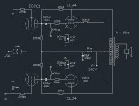
Can I please ask something regarding this older thread ?
SY said:
So, all things on the load side are important.
does that mean a scheme like this won't work ?
(a bit of Kirchoff, a bit of Kitic)
Empee
Can I please ask something regarding this older thread ?
SY said:
...One thing to be careful about is maintaining balance with the measurement- if you stick a scope probe on one output, you've unbalanced things. Use identical probes on each output. ALL bits related to the load, including the measurement apparatus, must be the same for balance. Two probes, dual channel scope.
So, all things on the load side are important.
does that mean a scheme like this won't work ?
(a bit of Kirchoff, a bit of Kitic)
Empee
Attachments
- Status
- This old topic is closed. If you want to reopen this topic, contact a moderator using the "Report Post" button.
- Home
- Amplifiers
- Tubes / Valves
- Balance in CCS Long Tailed Pairs