Hi Michael,
You wrote >>
here an annoying resonance follows a DIP in the frequency response <<
But is that rear 0ms trace the same frequency response we are so used to observing when a driver is energised via a steady sine ?
Where there is a resonant characteristic then there is a loss of energy during a first half cycle as a portion of drive becomes stored, then integrated within cone motion, and then released when the drive is removed.
In Posts#3546>3549 above, Lynn made significant comments relating to effects happening in 'time'.
Delayed effects arising within a waveform time period can modify dynamic waveform reproduction responses and propagation patterns in time, but cannot be electronically compensated for before they arise, as with this peak/dip.
A reproduction peak, or room positioning LS peak, might be mitigated by reducing drive at the problem frequency, but that can lead to further degradation of the first cycle of the dynamic responses, and to waveform induced positional shifting of generated imagery in time.
Hence poor driver/room characteristics cannot be EQed out (only optimised) and it is driver choice/mounting/positioning which counts.
We can have a good 'sine' response without having a good 'first cycle' (dynamic articulation) response, whereas if we take trouble to get the first cycle response correct, then the measured sine response is likely to be reasonable anyway !
Cheers ........... Graham.
Good point, Graham.
But frankly - I havent explored that any deeper –maybe someone else can comment on that more profund.
Taking some old datasheets I would expect that the "first half cycle behaviour" shouldn't be considered as a constant. My half educated guess would be that it's related to the Qts of the speaker. Qts past 0.7 should result in overshots if I am right.
The envelope of that first oscillations is kind of same thing like seen at (op)amps where it is usually called setting time and related to the phase margin.
To give a idea of what we are talking here, the comparison of two speakers may be helpful
D52 with a Qts of 0.53
30W54 with a Qts of 0.36
The comments on that data sheets about compression and the 120dB plots should fit perfect to that thread.
Greetings
Michael
But frankly - I havent explored that any deeper –maybe someone else can comment on that more profund.
Taking some old datasheets I would expect that the "first half cycle behaviour" shouldn't be considered as a constant. My half educated guess would be that it's related to the Qts of the speaker. Qts past 0.7 should result in overshots if I am right.
The envelope of that first oscillations is kind of same thing like seen at (op)amps where it is usually called setting time and related to the phase margin.
To give a idea of what we are talking here, the comparison of two speakers may be helpful
D52 with a Qts of 0.53
30W54 with a Qts of 0.36
An externally hosted image should be here but it was not working when we last tested it.
An externally hosted image should be here but it was not working when we last tested it.
The comments on that data sheets about compression and the 120dB plots should fit perfect to that thread.
Greetings
Michael
Yes, this "wrong" lead-in part of the waveform is a consequence of the highpass function (and, with a real driver, also of it's lowpass behaviour) applied to a non-sinusodial input (the sudden start of sine is not sine anymore, spectrally). The higher the Q of the 2nd order highpass, the longer it takes for the wave to settle. Unfortunately any highpass shows a step response overshoot, the magic Q value only applies for the lowpass function and there it isn't 0.71 (this only yields maximum flat amplitude frequency response, it's 0.50 (aperiodic response). Therefore, at the sudden start of sine running through a highpass we have two events, an intitial ringing/overshoot and a more or less slow build-up of amplitude. The overshoot/ringing only is visible when we are below the corner frequency, otherwise is masked by the amplitude. To test effects that are really a function of driver nonlinearities etc, one might better use sine bursts with raised cosine envelope which have a known and benign spectrum.mige0 said:But frankly - I havent explored that any deeper –maybe someone else can comment on that more profund.
Taking some old datasheets I would expect that the "first half cycle behaviour" shouldn't be considered as a constant. My half educated guess would be that it's related to the Qts of the speaker. Qts past 0.7 should result in overshots if I am right.
Linkwitz has some graphs showing these relationships:
http://linkwitzlab.com/filters.htm#9
And textbook highpass filter simulations confirm this perfectly.
- Klaus
Hi KSTR,
Thanks for your Linkwitzlab link.
The last set of drawings in section 9 show EQ controlling Fp=55Hz with Qp=1.2, however the first cycle dynamics are cannot be improved due to the higher driver Qp figure.
If a LF driver of lower Qes, lower Fs and low moving mass is used, especially on an open baffle, then the first cycle is much less degraded, any subsequent resonance less troublesome, and the dynamic response more accurate.
Cheers ...... Graham.
There are a few things to take note of when looking at CSDs:
1. When two drivers have pretty much the same effeciency and frequency response, the driver that decays slower will sound louder, the driver that decays faster will sound cleaner.
2. Since not all frequencies will have the same rate of decay, for frequency ranges that decay slower, you will notice non-percussion instruments in these ranges will sound more pronounced. In some cases this may create the illusion of having more detail which may not be correct representation of the recording but may be preferred by some listeners.
Maybe I misread you, but do you say the composite response, driver+correction, doesn't follow the product of the individual transfer functions? Assuming linear time-invariant systems (which is to be taken with a grain of salt wrt drivers) this initial "error" is only a matter of the combined transfer function.Graham Maynard said:Thanks for your Linkwitzlab link.
The last set of drawings in section 9 show EQ controlling Fp=55Hz with Qp=1.2, however the first cycle dynamics are cannot be improved due to the higher driver Qp figure.
I've attached a 28Hz Critical/Aperiodic (Q=0.50) 2nd order highpass time response, with 100Hz test frequency, which gives the same frequency ratio as in the Linkwitz example. All in all a 1:1 copy of the Linkwitz graph, isn't it? The perfect theoretical response for HP2 with Q=0.5 and a 3.5:1 freq ratio. If you have that conditions with a real system, this will be the response, regardless of system type (OB/CB/BR/...), provided that the system is well executed.
- Klaus
Attachments
Addendum, even one decade away from the filter frequency the ideal HP response still isn't a "copy" of the input waveform. We have to say goodbye to that, unless we go way up in frequency. This "error" is, BTW, a common source of confusion in distortion measurements, be in in reality or under simulation, you have to wait until things have settled.
- Klaus
- Klaus
Attachments
"1. When two drivers have pretty much the same effeciency and frequency response, the driver that decays slower will sound louder, the driver that decays faster will sound cleaner."
How much of a difference in the decay rate is audible as a change in loudness?? 2 ms? 10ms? 30ms??
Rob")
How much of a difference in the decay rate is audible as a change in loudness?? 2 ms? 10ms? 30ms??
Rob
soongsc said:2. Since not all frequencies will have the same rate of decay, for frequency ranges that decay slower, you will notice non-percussion instruments in these ranges will sound more pronounced. In some cases this may create the illusion of having more detail which may not be correct representation of the recording but may be preferred by some listeners.
Maybe I'm just thick, but isn't exactly this what is referred to as "coloration" ?
For example smth like this ?
I cannot quantify exactly how much difference is audible because not enough listener sampling is done, the if you look at the CSDs below, the one on the bottom will sound the loudest.Robh3606 said:"1. When two drivers have pretty much the same effeciency and frequency response, the driver that decays slower will sound louder, the driver that decays faster will sound cleaner."
How much of a difference in the decay rate is audible as a change in loudness?? 2 ms? 10ms? 30ms??
Rob
An externally hosted image should be here but it was not working when we last tested it.
Note that normally I compare with different drivers in each of thw two channels.
Yes, this is coloration. But I think using the simple term does not explain what's going on.FlorianO said:
Maybe I'm just thick, but isn't exactly this what is referred to as "coloration" ?
For example smth like this ?
Conical horns
Any up-to-date survey of horn technology must include the new conical midrange horns, in my opinion. The RCA guys did serious study of conicals in the 1950s, and appreciated their technical advantages. They decided to go with exponential primarily because of size/cutoff considerations. Bill Woods, who has been designing horn speakers for thirty years, has focused on the conical shape exclusively in recent years for audiophile (as opposed to prosound) listening.
When a thirty-year horn pro says "conicals are the way to go," it's worth giving it a try. There are technical advantages regarding conicals, most of which I don't understand. But, I have heard Bill's 700hz horns and 300hz horns, with vintage drivers. The difference between them a vintage exponential/multicell and recent round tractrix is quite dramatic.
I concur that there is very little "horn sound" with a conical, which Bill attributes to the lack of waveform bending caused by curved sidewalls. Also, they are pleasingly non-directional, like a CD horn or multicell, unlike most round horns with their "head in the vise" teenyweeny sweet spot. I was listening to a vintage driver on the 300hz horn just yesterday, confirming my memory that this is an excellent combination.
Bill's horns are stonkingly well made, of cast aluminum.
I have no business interest in the Acoustic Horn horns, but they would be my first choice, at that price point, were I building a system now. Tom Danley also uses a conical contour these days. While I expect many will be troubled by the idea that horn nirvana can be obtained with a cast-aluminum version of a cheerleader's megaphone -- it is a lot more sexy to have a pile of complex curve maths -- I would suggest giving it a try before forming one's opinions.
Here's Bill's description from his site acoustic-horn.com:
The conical horn is the simplest horn shape. The cross-section increases linearly, like a cheerleader's megaphone. Compared with all other horn flares, conical horns have a precisely defined radiation characteristic. Conical horns, manifest a homogeneous radiation characteristic over a wide frequency range. There is no disruption to the wavefront as it moves out towards the horn mouth. The "horn sound" is nil with a conical horn. Because the wavefront has a smooth passage, it has perfect phase.
Another advantage is that the cross-sectional area in the vicinity of the horn throat increases more rapidly than for exponential horns. This thus reduces the sound pressure in the horn as well as distortions due to the compressibility of air.
What conical horns sound like....
Since conical horns have no curvature, the ever emerging wave is not deformed as it moves from the throat to the mouth. This means that there is a linear pressure change throughout the horn.
When this condition is met, the horn will have very low 'air column' distortion, or distortion cause by squeezing the air at the throat. Conical horn also have good phase response, due to the reason stated above.
In short, the conical horn amplifies the sound, with the least disruption to the sound wave.
The sound of a conical horn system has very little trace of the "honky" sound usually associated with horn. Because the horn has good phase response it can be crossed over with another horn or direct radiator very smoothly.
Directivity is another positive feature of a conical horn. The sound goes where you want, cutting down unwanted room reverberation.
The end result of all of this is that when you hear a horn system, it has a very lifelike sound. Bells and horns sound like the real thing. Nothing comes close the sound of a cello (especially the Mercury recordings with Starker.)
Directivity seems to be an important factor. Some feel that omni direction is best, some feel a controlled constant directivity is best, some say the focussed beam is best. I was experimenting holding a pillow in front of my face to reduce the amount of sound from one speaker reaching the opposite ear, and I can say the the focus was much improved. But I also can understand what Linkwitz was trying to explain in his AES presentation.
Regarding the conical horn there is a fatal flaw in the description above.
A spherical wavefront does in fact propagate down a conical horn or waveguide unchanged by the boundaries, at least up to the mouth where of course it will have to change from the mouth diffraction. But all devices share this problem. However the matching of wavefronts at the throat has been ignored. There simply are no practical sources that generate spherical wavefronts. Hence the wavefront allowed to propagate by the conical horn has to be seriously altered right at the throat where it joins with the source. If this source is a compression driver then that wavefront is (to a first approximation) flat and it will have to diffract at the throat to become spherical for propagation down the conical horn. This generates strong internal reflections and a very high content of Higher Order Modes.
Ignoring the mating of the horn wavefront with the wavefront from the source is a typical problem in the literature. The source and the waveguide couple very strongly - becoming one system in fact - and this aspect of any horn or waveguide design is critical. OS waveguides become conical away from the throat by coaxing the flat wavefront from the source into a spherical wavefront as required by the final conical portion. This is done with the least amount of diffraction and reflection possible. Hence in a very real sense the OS actually does what the conical is incorrectly claimed to do in the above description.
gedlee said:Regarding the conical horn there is a fatal flaw in the description above.
A spherical wavefront does in fact propagate down a conical horn or waveguide unchanged by the boundaries, at least up to the mouth where of course it will have to change from the mouth diffraction. But all devices share this problem. However the matching of wavefronts at the throat has been ignored. There simply are no practical sources that generate spherical wavefronts. Hence the wavefront allowed to propagate by the conical horn has to be seriously altered right at the throat where it joins with the source. If this source is a compression driver then that wavefront is (to a first approximation) flat and it will have to diffract at the throat to become spherical for propagation down the conical horn. This generates strong internal reflections and a very high content of Higher Order Modes.
Ignoring the mating of the horn wavefront with the wavefront from the source is a typical problem in the literature. The source and the waveguide couple very strongly - becoming one system in fact - and this aspect of any horn or waveguide design is critical. OS waveguides become conical away from the throat by coaxing the flat wavefront from the source into a spherical wavefront as required by the final conical portion. This is done with the least amount of diffraction and reflection possible. Hence in a very real sense the OS actually does what the conical is incorrectly claimed to do in the above description.
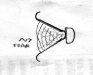
Ii this the right concept if I understood at all?
Attachments
So, does this technique dealing with vertical directivity using a 40 degree CD horn have any valaidity?
http://www.audioroundtable.com:80/PiSpeakers/messages/11054.html
http://www.audioroundtable.com:80/PiSpeakers/messages/11054.html
salas said:
Ii this the right concept if I understood at all?
Not sure that I understand your drawing. If this an OS waveguide or a conical horn?
Norris Wilson said:So, does this technique dealing with vertical directivity using a 40 degree CD horn have any valaidity?
http://www.audioroundtable.com:80/PiSpeakers/messages/11054.html
This is just a rewrite of John Eargle's AES paper about the design of the 4430. When it was written some 20 or more years ago it was state of the art. Where John still alive today he would be using an OS waveguide in this application, and the same principles would apply. John was always a big supporter of my waveguide concept and John and I worked together back in the early 90's developing designs for JBL.
The horn in the 4430's was CD, but it was done with diffraction. It was the desire to imporve on the basic 4430 design with a modern waveguide that led to my Summa's. I had 4430's in my listening room for almost 20 years. But modern waveguides are a vast improvement on this very good basic design.
- Home
- Loudspeakers
- Multi-Way
- Beyond the Ariel