Goto said:
In terms of the kit, I would suggest if the option is available, to add polarity markers on the pcb screen for the LEDs. Anyone without much experience in building up boards might get caught out as the board currently seems to assume you can trace the circuit against the schematic.
Mark
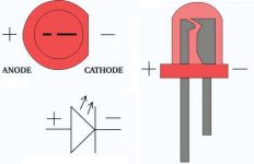
Mark, on my boards the LED locations (D1-D4) are indicated via a circle with a flat edge on one side? I've always taken this to be a match for the flat edge of the LED or failing that the shorter negative cathode leg?
(Failing that look inside the LED and the cathode (negative) is the one with the little cup shape) Also if you look closely one hole is square - which I've again taken to means negative or cathode. Is your board different?
Of course I may be going mad...
rjbaldwin said:
Mark, on my boards the LED locations (D1-D4) are indicated via a circle with a flat edge on one side? I've always taken this to be a match for the flat edge of the LED or failing that the shorter negative cathode leg?
(Failing that look inside the LED and the cathode (negative) is the one with the little cup shape) Also if you look closely one hole is square - which I've again taken to means negative or cathode. Is your board different?
Of course I may be going mad...
RJBaldwin, you are of course, correct, but I can never remember whether the flat side is Cathode or Anode so I am guessing there are other idiots like me out there who only dabble in this foolishness and need things spelt out as clearly as poss.
Mark
ef
Thanks PElliot for the link - which in no way would help, looking at the board in question. Thanks for your input anyway.
I offered comment on a design, which is the reason betas get released. If Russ chooses to act or ignore my comments, that's his perogative. The polarised caps on the board get marked with a + sign, I am just saying it would make orienting the LEDs that little bit easier too.
rolls said:
Hello Russ
I thank you for this answer. This was not a hidden critic, but just interest. I would like to know this, because my Buffalo is battery driven, but the 1.2V reg is still in place. By the way, I have thought that I always read both threads, and I feel sorry when I missed a part.
regards
Andre
How is it performing on the battery? What type of battery are you using?
a different buffalo
I wondered whether there would be any reaction to the word battery. The idea is from Mr. Serge Schmidlin, Audio Consulting in Switzerland, who does not use mains any more. During a visit we made a few tests. Back home I started building a second buffalo. At the same time Mr. Schmidlin wound a prototype of a suitable I/V transformer. So I have the buffalo in passive current mode. My first test with transformers were with the first buffalo and an S&B Mc step up, silver winding. No chance for IVY. The new transformer is even better, less grain, more pixels, even with copper windings. I think it will become a masterpiece when wound in cryo-silver. Unfortunately not many transformers are suitable for this task. Primary resistance should be low, as in a MC step-up, but at the same time they should give at least 2 Volts output.
The i/v resistor is also very important. At first I used a normal 5 cent metal film, then I bought Vishay bulk metal foil, for Euro 15!! What a difference! I didn't believe it.
Another lesson I have learnt: The best regulator is no regulator! I removed Reg1 and the opamp, Reg2 is still in place. The batteries are Mr. Schmidlins Baby, so please don't ask at the moment. I can only say that cheap lead batteries with regulators won't do the job.
Outside my home the dac has already performed in 4 different places. I always had the "mains" buffalo with me, but there was just one choice, the transformer battery dac plays in another league. One session was in Germany. Buffalo played with 300B amps and a fantastic Voice of the Theatre with a wood "Dauphin" horn. Sorry, but I have also heard many bad "Voices". There were a few vinyl lovers, there is a Garrard with Ortofon arm and cartridge. They listened to music for more than four hours, without playing a single record! CD Transport was Kenwood DP-X9010.
Just one of the virtues of the battery dac, it remains transparent, even in the most complex passages, where other dacs start to become painful. Until now I have always blamed the CD.
Last I would like to thank Russ and Brian for the chance we have got to use this excellent chip.
Andre
khundude said:
How is it performing on the battery? What type of battery are you using?
I wondered whether there would be any reaction to the word battery. The idea is from Mr. Serge Schmidlin, Audio Consulting in Switzerland, who does not use mains any more. During a visit we made a few tests. Back home I started building a second buffalo. At the same time Mr. Schmidlin wound a prototype of a suitable I/V transformer. So I have the buffalo in passive current mode. My first test with transformers were with the first buffalo and an S&B Mc step up, silver winding. No chance for IVY. The new transformer is even better, less grain, more pixels, even with copper windings. I think it will become a masterpiece when wound in cryo-silver. Unfortunately not many transformers are suitable for this task. Primary resistance should be low, as in a MC step-up, but at the same time they should give at least 2 Volts output.
The i/v resistor is also very important. At first I used a normal 5 cent metal film, then I bought Vishay bulk metal foil, for Euro 15!! What a difference! I didn't believe it.
Another lesson I have learnt: The best regulator is no regulator! I removed Reg1 and the opamp, Reg2 is still in place. The batteries are Mr. Schmidlins Baby, so please don't ask at the moment. I can only say that cheap lead batteries with regulators won't do the job.
Outside my home the dac has already performed in 4 different places. I always had the "mains" buffalo with me, but there was just one choice, the transformer battery dac plays in another league. One session was in Germany. Buffalo played with 300B amps and a fantastic Voice of the Theatre with a wood "Dauphin" horn. Sorry, but I have also heard many bad "Voices". There were a few vinyl lovers, there is a Garrard with Ortofon arm and cartridge. They listened to music for more than four hours, without playing a single record! CD Transport was Kenwood DP-X9010.
Just one of the virtues of the battery dac, it remains transparent, even in the most complex passages, where other dacs start to become painful. Until now I have always blamed the CD.
Last I would like to thank Russ and Brian for the chance we have got to use this excellent chip.
Andre
mikelm said:Hi Andre
Is the resister before or after the transformer ?
mike
Hello Mike
I have tried both ways. First with 30 Ohms at the buffalo output. Now I have 1K on the secondary for about 500mv output, I don't need more. I think it is better when the transformer is involved in i/v, because in the i/v resistor nearly all the power from the dac will be burnt.
Andre
Goto said:
RJBaldwin, you are of course, correct, but I can never remember whether the flat side is Cathode or Anode so I am guessing there are other idiots like me out there who only dabble in this foolishness and need things spelt out as clearly as poss.
Mark
Mark, I agree with marking the board for LED polarity '+", it certainly couldn't hurt, and I often forget which way round components go as well... so, no offence meant to you ;-) I only added the LED note so others would not have the same problem.
Russ
Hello rolls,
I noticed you are experimenting with different output stages.
Are you using the balanced chip in se mode? If you are using the chip in SE mode, have you placed a load to the unused Out-?
Batteries are difficult to make them work well (to make large improvements). I don't have the patients nor notable experience with this. In theory it would would work very well. In my reality (opamp project) it did not.
I would imagine it (placing the res after the primary) sounds better. If the transformer is matched well why immediately load?
Great information here! I'm patiently waiting to join the "Buffalo Club"!
Cheers,
MV
P.s. the + of led is the small (usually) anode side. On the board indication is a design "nice to have" but you should be able to this without problems on the pc board.
mavallarino said:Hello rolls,
I noticed you are experimenting with different output stages.
Are you using the balanced chip in se mode? If you are using the chip in SE mode, have you placed a load to the unused Out-?
Batteries are difficult to make them work well (to make large improvements). I don't have the patients nor notable experience with this. In theory it would would work very well. In my reality (opamp project) it did not.
I would imagine it (placing the res after the primary) sounds better. If the transformer is matched well why immediately load?
Great information here! I'm patiently waiting to join the "Buffalo Club"!
Cheers,
MV
Hello MV
I use the chip in normal balanced mode. I have learnt that it should and can operate without dc current. That's the reason they use a reference input on IVY2. It is even easier with a tranny, because each input is the reference for the other, no midpoint, no dc.
regards
Andre
rolls said:
Hello MV
I use the chip in normal balanced mode. I have learnt that it should and can operate without dc current. That's the reason they use a reference input on IVY2. It is even easier with a tranny, because each input is the reference for the other, no midpoint.
regards
Andre
It is true that it is good to operate the DAC at AVCC/2 output bias. But loading it directly with a transformer primary means you are using it as a voltage source, not a current source. This means that the outputs of the DAC will not stay at AVCC/2 but modulate with the signal.
The purpose behind our new I/V converters is to keep that bias as close as possible to AVCC/2 regardless of the signal.
") That is why it has to be a very low impedance.
That is why it has to be a very low impedance.Still I have no problem with using transformers on output, its just not something I have done much of yet. I probably would not use one directly after the DAC, but after something like IVY II. Or Buffalo32S to turn the balanced output to single ended and provide good isolation.
Cheers!
Russ
Russ White said:
It is true that it is good to operate the DAC at AVCC/2 output bias. But loading it directly with a transformer primary means you are using it as a voltage source, not a current source. This means that the outputs of the DAC will not stay at AVCC/2 but modulate with the signal.
The purpose behind our new I/V converters is to keep that bias as close as possible to AVCC/2 regardless of the signal.
Still I have no problem with using transformers on output, its just not something I have done much of yet. I probably would not use one directly after the DAC, but after something like IVY II. Or Buffalo32S to turn the balanced output to single ended and provide good isolation.
Cheers!
Russ
Hello Russ
I use an 1:10 transformer with a secondary load of 1k. Reflected load will be 10 Ohms, slightly more because of the primary resistance. So you still think this is voltage mode? Is there a mistake in my design?
regards
Andre
rolls said:
Hello Russ
I use an 1:10 transformer with a secondary load of 1k. Reflected load will be 10 Ohms, slightly more because of the primary resistance. So you still think this is voltage mode? Is there a mistake in my design?
regards
Andre
Hi Andre,
It's a design decision.
Put a scope at the outputs of the DAC itself and you will see it clearly.
I don't think its a mistake, but yes it is voltage mode. And it will still modulate the DAC outputs. Is that good or bad, well I don't know. I do know it makes the DAC itself measure worse . Do whatever you think sounds good.
One nice thing would be to use something like the Counterpoint and then a 1:1 transformer on the output to turn the balanced signal to single ended. This will eliminate the turn off transient one would see if they took just a single side of the balanced output and GND. The input impedance of the Counterpoint is a few milliohms.
Cheers!
Russ
Russ White said:
Hi Andre,
It's a design decision.
Put a scope at the outputs of the DAC itself and you will see it clearly.
I don't think its a mistake, but yes it is voltage mode. And it will still modulate the DAC outputs. Is that good or bad, well I don't know. I do know it makes the DAC itself measure worse . Do whatever you think sounds good.
One nice thing would be to use something like the Counterpoint and then a 1:1 transformer on the output to turn the balanced signal to single ended. This will eliminate the turn off transient one would see if they took just a single side of the balanced output and GND. The input impedance of the Counterpoint is a few milliohms.
Cheers!
Russ
Hello Russ
Thank you for your help. From the listening experience it can't be voltage mod, because the buffalo sounds much better with 1:10, 1k loaded, than with 1:1. But I will look at the scope. When the transformer had a 3.15V midpoint, we would nearly have a duplicate of the IVY input, nearly because "winding resistance" with IVY goes to zero.
Battery and passive sounds strange. I didn't believe it as well. I was invited by a friend, who has his buffalo built in his beautiful Primare Cd player, to a dinner. He was not really keen on my battery dac and another session. Then he listened for an hour and said: Now I have a problem! (There is no room for batteries in the Primare)
regards
Andre
Russ
Operating in balanced mode, I get a very small turn on/off pop. Nothing to worry about.
Dc voltages measure between each balanced output and gnd all come in the range 10 - 40 millivolts and don't appear to trouble my Hypex power amps, even when running the Volumite at zero attenuation.
If I change the RG1 & 2 resistors to give more voltage swing at the output, are those dc offsets likely to change?
Mark
- Status
- This old topic is closed. If you want to reopen this topic, contact a moderator using the "Report Post" button.
- Home
- More Vendors...
- Twisted Pear
- Buffalo DAC (ESS Sabre 9008)