I just acquired a nice clean "looking" Pioneer PL-514 from eBay. It will fit in my console with a little work and relocation of some items. It has a single sliding panel top now but I may make a hinged flip up top and open up the whole top area for easier access to the components.
Is there any reason a reciever can't be mounted on its back, that is to say with the display and controls facing upwards and the back facing the floor? I would think the airflow for removing heat might be the biggest concern but a well placed fan should fix that issue.
Bacon665, what have you built with tubes? You sound like you have been working with them for years. I think you would really enjoy teaching me all you know and helping me mod my SEP to RH84 status. Your email function is off.
901Fixer said:Is there any reason a reciever can't be mounted on its back, that is to say with the display and controls facing upwards and the back facing the floor?
No reason.
dave
i started out three years ago when someone gave me a halicrafter sx-21 and then i started fixing old radios. Ive also restored one RCA victrolla. so ive been where you are. as for what ive built from scratch being an underfunded HS student iv built a headphone amp thats about 90% complete and im working on plans for monoblocks to directly drive a set of ESLs.
as far as space goes you can do some really nice stuff without using a 90 degree bracket to slap something on the back.
if you own a saw or know someone who does you can place a board in the back of that radio between the speaker. then run all the controlls and the display to the top (or not if you find one that doesnt have a display) talk a volt meter though your amp and see what the lowest voltage you can find is (i suspect 6 volts)
From there walmart used to sell these little fm radios for like a dollarwhich ran off of two AAA batteries. This can be mounted somewhere just on the interior sidewall of the case without a great deal of fabrication. use a voltage divider to run a 3volt or two 1.5 volt lines off the 6volt heater.
These little things are simple the antenna is on the board there two buttons seek and reset and theres a volume pot.
Since currently this thing is mono take the audiojack off (unsolder it and keep it for another project) bridge the left and right channels then run an outwire (so you dont forget where it goes or was) unsolder the buttons and through them in the trash (theyre worthless as far as reuse goes) find either two one position switches or one dual position switch (through hole) you can go to radioshack and explain what your doing and most of them will be able to help. the potentionmeter is also a switch on most of these so you can save it for bias adjustments on something else but i would replace it especially since you dont need the second switch.
Now all thats left is drill the holes for the switch(s) and the volume pot then wire its output to the amp and no one will ever know it wasnt integrated except the people who view these forums and the ones you tell (grandkids peeking behind it?)
//edit
i completely forgot you asked about email forested665@gmail.com
Grandkids? C'mon man, I'm not that old. 😀
I am tool rich. New table saw, router, chop/mitersaw, jigsaw, sawzall, 6-axis CNC machine, welder, sanders, air compressor, circular saws, etc. Maybe not the CNC machine yet.
Use-ability is key and although I like to tinker, the end result is what guides my decisions. With the lid closed, this console will look original or at least not chopped up. It will be usable in a real sense and sound good enough to listen to. This thing is really small though so I may have to get real creative.
the top lifts up right? because you can put whatever controls next to the record player on the inside.
did we ever find a model number for the thing?
wait... youve got a schematic for it... have you got a scanner? or know someone who does? if i can take a looksy at it this will make our lives easier.
did we ever find a model number for the thing?
wait... youve got a schematic for it... have you got a scanner? or know someone who does? if i can take a looksy at it this will make our lives easier.
The schematic is not of the amp but how it connects to the speakers, the turntable and the little light below "Magnavox" on one of the grilles. I can take a picture with my camera if you think it will help but it won't come off of the panel it is glued to, I tried and it started to rip.
Right now only the right half of the top slides open to reveal the turntable and the treble, loudness and bass controls. The left half of the top is fixed and the right side top panel slides underneath it, sorta like an ice cream cooler at the local Gas & Sip. The inside width is 37" so two modern components, turntable and reciever, will fit as 17" is standard.
I believe it is '61 or '62 vintage based on the numbers on the drivers. Thats about all I know as I have not found any other markings to indicate what it is. I did find a website dedicated to old radios and turntables, maybe I should give them a try.
Is it safe to say that different types of tube amps are just different combinations of the same parts? Different tube specifications but they all have tube sockets, transformers, pots, caps, resistors, a case and wiring correct? I saw a nifty looking tube amp somewhere on this site that had the transformers in a row down the center of the case from front to back and had the tubes on either side of the transformers mounted at a 45 degree angle. Really slick, maybe I can go that route with a dual RH84 or whatever would best drive these CTS drivers. I may need to get a new soldering iron.
most of these are point to point so they can be assembled however on the case or would.
And yes.. parts are common among amplifiers and other circuits.
But ill give you a good example using transistors.
These two circuits do the same thing but the transistor is working completely different. (and its technobabble i havent grasped yet)
theres several amps that have common tubes with yours but theyre wired different and have other componants or less. and you can also design/modify
was there a model number on maybe the turntable? did you check the underside? because i might be able to do a crosscheck with the units.
ill do some prowling later se if i can find it.
And yes.. parts are common among amplifiers and other circuits.
But ill give you a good example using transistors.
An externally hosted image should be here but it was not working when we last tested it.
These two circuits do the same thing but the transistor is working completely different. (and its technobabble i havent grasped yet)
theres several amps that have common tubes with yours but theyre wired different and have other componants or less. and you can also design/modify
was there a model number on maybe the turntable? did you check the underside? because i might be able to do a crosscheck with the units.
ill do some prowling later se if i can find it.
There was a number on the underside of the turntable, 523223-5 which is in Magnavox style but I haven't found it listed anywhere.
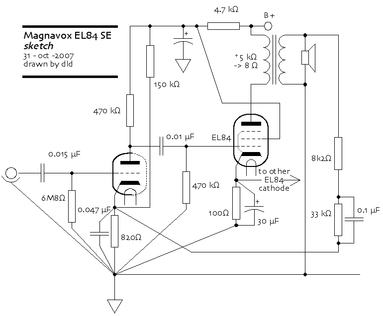
On the schematic there is the number EL1725-1 in one corner that does not pertain to any part of the schematic. The rest of the print is the schematic.
On the schematic there is the number EL1725-1 in one corner that does not pertain to any part of the schematic. The rest of the print is the schematic.
Attachments

Congrats i think your the owner of a 1968 magnavox mediteranian.
and they originally had a tuner in them.
check this ad for confirmation
from.
if so i will have something to work
and they originally had a tuner in them.
check this ad for confirmation
from.
An externally hosted image should be here but it was not working when we last tested it.
if so i will have something to work

acording to this thread... http://www.audiokarma.org/forums/archive/index.php/t-83333.html its used in everything
and i found the schematic to this generic amp here
http://gabevee.tripod.com/maggie.html
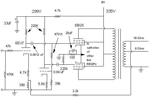
the 6eu7 is a high mu twin triode. from what ive seen it can be replaced with a more common 12A series.
and i found the schematic to this generic amp here
http://gabevee.tripod.com/maggie.html
the 6eu7 is a high mu twin triode. from what ive seen it can be replaced with a more common 12A series.
That is a push-pull amp... this one has 2 OPTs so that makes it an SEp... should be pretty similar to this one.
901 -- take this map, print it, and see if you can match the map to your amp -- some values will be different. It is a really good learning excersize.
Go here to look up the tube base info
http://tdsl.duncanamps.com/tubesearch.php
dave
901 -- take this map, print it, and see if you can match the map to your amp -- some values will be different. It is a really good learning excersize.
Go here to look up the tube base info
http://tdsl.duncanamps.com/tubesearch.php
dave
this is an odd amp no matter how you want to look at it. its got three transformer though i assume one is for power i figured the second was the centertap for push pull and the third the audio output transformer.
and theres a 4th tube not mentioned in either of the above schematics.
and theres a 4th tube not mentioned in either of the above schematics.
bacon665 said:and theres a 4th tube not mentioned in either of the above schematics.
6CA4 = EZ81 is the rectifier tube.
dave
Yes I am, thanks for axin'. I've been working on some woofer enclosures for my main system.
I have a Pioneer PL-514 turntable coming to replace the micromatic. I may see how it sounds thru the amp the way it is if nobody thinks thats a bad idea. I suppose my next step is to acquire all of the necessary items to make the upgrade to RH84, you got all that layin' around somewhere? Where do you get your tube supplies?
I have a Pioneer PL-514 turntable coming to replace the micromatic. I may see how it sounds thru the amp the way it is if nobody thinks thats a bad idea. I suppose my next step is to acquire all of the necessary items to make the upgrade to RH84, you got all that layin' around somewhere? Where do you get your tube supplies?
i have a good chunk of parts from where ive trashed other stuff. i usually buy what i need where i can get it cheap. I will take a look through the RH84 if i remember many people modified this thing due to microphonics.
looking at the schematic i would suggest a different tube other then the ECC B1 because your just wasting a triode until you do dual monoblocks. The powersupply filtering looks kinda... iffy and is for a 220 line (on the site im looking at) If you have a multimeter i suggest finding the outputs of your power transformer and seeing what all the voltages are. you may just want to reuse your current powersupply and if you look at the price of power transformers might still decide just to modify it if it currently doesnt meet the requirements. considering these are roughly the same tubes in both amps i suspect it will work just fine.
To be quite honest this looks like a downgrade from the current setup.
bacon665 said:i would suggest a different tube other then the ECC B1 because your just wasting a triode until you do dual monoblocks.
Why are you wasting an 'AT7? 1 triode per channel, 1 tube. The ECC81 has complentary distortion charachteristics to the EL84, so this combo works well. Eli uses the same trick in El Cheapo.
RH84 is designed to work quite well with even mediocre iron.
Just build it... power supply is "bring what you got"
dave
I didnt mention the at7. His set up is currently single channel. I didnt know if he was going to stereo or not. For it to remain mono both the ECC81 and the AT7 are a waste because only one half of the triode is used. I suppose p1 can be tied to g2 and p2 be used as the output (using both triodes as a single preamp) but that would completely change the characteristics of the amp.
- Status
- Not open for further replies.
- Home
- Loudspeakers
- Multi-Way
- Buffet style china cabinet hutch enclosure.