Hi,
I have finally decided on the flavour of 300b I want to build, and it is the Loesch Legacy amp with a C3m driver. But I want to start off with a simpler more traditional power supply. I have a couple of questions about this that I would love to understand better, so thought to ask here.
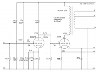
1) In the Legacy amp below, the 300b operating values seem to be set for a 3.5k transformer. Do you agree, and if so what are the implications of replacing the Audion 2.4k transformer with a Lundahl 3.5k/90ma transformer?

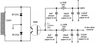
2) And if I use the power supply from the 'New Reference Amplifier' on audiodesignguide.com (below), can I just swap out the mains transformer for a 375v one to give a 420v nominal supply? (And what does 'nominal' mean? If I do the current/voltage calculations on the legacy amp, I calculate that the B+ above the driver stage to be 390v not the 420v given)

Thank you sooooooo much for any help, and keep well.
I have finally decided on the flavour of 300b I want to build, and it is the Loesch Legacy amp with a C3m driver. But I want to start off with a simpler more traditional power supply. I have a couple of questions about this that I would love to understand better, so thought to ask here.
1) In the Legacy amp below, the 300b operating values seem to be set for a 3.5k transformer. Do you agree, and if so what are the implications of replacing the Audion 2.4k transformer with a Lundahl 3.5k/90ma transformer?

2) And if I use the power supply from the 'New Reference Amplifier' on audiodesignguide.com (below), can I just swap out the mains transformer for a 375v one to give a 420v nominal supply? (And what does 'nominal' mean? If I do the current/voltage calculations on the legacy amp, I calculate that the B+ above the driver stage to be 390v not the 420v given)

Thank you sooooooo much for any help, and keep well.
1) Higher load impedances (for triodes) give slightly lower peak output power and slightly lower distortion and better speaker damping. It's entirely your call.
2) Nominal means "Good luck, and thanks for all the fish." But seriously, it means you don't have enough information to pretend to have 10% tolerances there. If you're bound and determined to actually design a B+ supply, you need real numbers, including specs of the power transformer, and a program called PSUD (I hope that's the right name - if not somebody will fix it for us.)
The proposed power supply design looks slightly wasteful, and the GZ34 is drawn backwards, and there's no decoupling for the driver stage, and there's a weird capacitor from B+ to driver G2, but the worst part is that it doesn't show the filament supply for the DHTs. The amplifier circuit demands clean DC there.
YOS,
Chris
Thank you. I can sort out the GZ34 and I have the filament supplies, but the two points you raise above around decoupling and the odd G2 cap I thought were clever design choices by Mr Loesch. I don’t know enough to design my own amp and yet this seems a respected amp design for the 300b.there's no decoupling for the driver stage, and there's a weird capacitor from B+ to driver G2
Difference of "nominal" 400V or 420V is negligible considering the mains power voltage fluctuation (+/- 5...10%).
In this design -in the PSU- the main bottleneck is the power transformer, then the rectifying structure.... and the other part of whole PSU. :-(
Producing -good- 2x 90mA isn't easy job, requiring properly selected parts.
As you can see, the Legacy requires hardened PSU.
http://community.fortunecity.ws/rivendell/xentar/1179/projects/legacy/Legacy.html
BTW I'm not a fan of pentode C3m.
It has engaging tone (due to the mesh anode), but requiring 20V heater supply, pentode mode has large output impedance, and in pentode mode -as many high gain tube, if you make the layout not enough attention- tend to oscillate.
In triode mode hasn't enough gain to use in two stage amplifier.
From these points of view IMHO C3g is better tube:
- 6.3V heater;
- enough gain in triode mode;
- enough low output impedance in triode mode.
Last edited:
I recommend Rod Coleman regs for filament supplies for the 300b. I feed mine with a 230v: 12v+12v transformer. I reasoned that a 50VA EI transformer would be OK for this, but it gets quite hot. I now use a 100VA transformer. Build that and that's one part of the design out of the way.
If you don't want to use C3m in pentode there are a few options for triode. There are some current threads on that. You need a mu of 30 or more, maybe 40, depending on your system and if you have any gain in a preamp.
You don't need to follow the original schematic exactly. Thorsten regularly updated his ideas and this is an early design of his.
Thanks for that.
I was intrigued by the 10u/22u path in parallel with the 22k/12k voltage divider. Is the purpose of this to follow PS ripple?
Re the power supply decoupling for the driver stage, I assumed that the 12k above the C3M anode did that job.
I was intrigued by the 10u/22u path in parallel with the 22k/12k voltage divider. Is the purpose of this to follow PS ripple?
Re the power supply decoupling for the driver stage, I assumed that the 12k above the C3M anode did that job.
The output transformer generally constitutes a bottleneck. There is a great advantage in going for the high quality Lundahl. A higher primary inductance means higher output power and higher distortion.
I would lower the operating voltages of c3m.
I would lower the operating voltages of c3m.
Ah, good spot. My mistake. The anode voltage should be 220v not 275v. Any thoughts on the role of the two capacitors by the driver?
A higher primary inductance means higher output power and higher distortion.
Where do you get these ideas? They're so unique!
daanve, instead of complaining, please refute the assertions if you can. Disagreement is not refutation.
All your statements are not refutations. 😛Disagreement is not refutation.
Have a look at the WE operating points for 300b. They're posted regularly here - I don't have the link handy - does anybody have it?
WE
4300 data at 400V
4300 data at 400V
Attachments
Last edited:
I have the specs and have used a load line calculator to calculate operating point and grid bias voltage etc. I just wanted to use a simpler power supply (have now got PSUD so have calculated that), so just the driver stage to get my head around. Still intrigued by the 2 caps.
- Home
- Amplifiers
- Tubes / Valves
- C3m 300b SET question
