[Re: Dexa] Does anyone know what IC they're based on?
Check out the Vregs from LDOVR which are based on 2 different ICs:
https://www.ldovr.com/category-s/113.htm
Can you see them in my screenshot in post #9?
Yes, make them as large as possible, and also consider adding more in parallel in any nearby empty space...
they are two Elna Silmic II 2200uf 25v , but those have been discontinued.
what else can i put in there , in parallel?
thanks
The Panasonic Os Cons?
should I bypass the caps on the fixed outputs for both L and R channels?
https://www.manualslib.com/manual/2859921/Marantz-Hd-Dac1.html?page=60#manual

should I bypass the caps on the fixed outputs for both L and R channels?
https://www.manualslib.com/manual/2859921/Marantz-Hd-Dac1.html?page=60#manual
The caps should be left alone. Do not change them. Silmic II are very good and they do contribute a lot towards that Marantz sound, which is pretty pleasing and spacious.
The only way you are going to improve the sound is to look at implementing/using low noise voltage regulators, like already suggested (I think...) above. That will bring a meaningful improvement to sound reproduction. You could connect multiple lower-current voltage reg PCBs in parallel, to double the current capability... here are 2 x 1A LT3045 LDOVR regs connected in parallel, for a 2A total current capability. The 2A is not really needed; the paralleling is done to halve the heat dissipation and ensure the voltage reg IC's work within their nominal specifications.


Good luck.
The only way you are going to improve the sound is to look at implementing/using low noise voltage regulators, like already suggested (I think...) above. That will bring a meaningful improvement to sound reproduction. You could connect multiple lower-current voltage reg PCBs in parallel, to double the current capability... here are 2 x 1A LT3045 LDOVR regs connected in parallel, for a 2A total current capability. The 2A is not really needed; the paralleling is done to halve the heat dissipation and ensure the voltage reg IC's work within their nominal specifications.
Good luck.
thank you so much man. @Extreme_Boky
yeah it was done by a member on this thread.
i PMed him and he has since sold the unit , but he changed the two regulators for the digital and analog for Dexa low noise ones.
but you say I can connect more in parallel with the ones already on the board?
so I don’t have to unsolder the old ones?
below is the thread where he mentioned it.
https://www.diyaudio.com/community/threads/the-good-and-the-bad-of-the-marantz-hd-dac1.266335/
@Extreme_Boky
Here are the two voltage regulators mentioned , which I circled in red
IC99 and IC98
One is three pin and the other is 4 pin.
can I solder those low noise regulators onto the ones one the board circled so I don’t have to take them out?
cheers

Here are the two voltage regulators mentioned , which I circled in red
IC99 and IC98
One is three pin and the other is 4 pin.
can I solder those low noise regulators onto the ones one the board circled so I don’t have to take them out?
cheers
..... but you say I can connect more in parallel with the ones already on the board?
so I don’t have to unsolder the old ones?
NO, that's not what I said. I said you could use the two (new/additional/better spec-ed) voltage regs in parallel... in place of the typical TO220 voltage regs (or, you could add the additional very low-noise voltage regs where needed... )
Based on your responses, I strongly suggest that you get someone to do these mods for you.... exactly what you intended to do in the first place
") .
. I thought I'd push you in the right direction... but maybe start with something easier... like one of the diyAudio Store FW clones.. or similar.
You guessed correctly. And thanks so much.
@Extreme_Boky
i am going to get someone to do the mods.
So besides those two voltage regulators which will help with the DAC and analog side.
can I do anything to the headphone part to improve it?
power wise or parts wise?
could I send it to you to perform the mods?
much appreciated
@Extreme_Boky
i am going to get someone to do the mods.
So besides those two voltage regulators which will help with the DAC and analog side.
can I do anything to the headphone part to improve it?
power wise or parts wise?
could I send it to you to perform the mods?
much appreciated
The unit has two amps (I think... one is the pre-map, and the other is the headphone amp). The voltage regulators I suggested could be installed instead of the original voltage regulators... pretty much everywhere... wherever there's a (cheap) voltage reg used originally by Marantz. The sound improvement will be substantial (and one that will show in measurements as well, if that is important to you...)
I stopped doing the modifications to Hi End gear a long time ago... besides, I live in Sydney... so the total cost of modifications would be more than the unit costs brand new.
Find someone close to you... that will be much cheaper.
I stopped doing the modifications to Hi End gear a long time ago... besides, I live in Sydney... so the total cost of modifications would be more than the unit costs brand new.
Find someone close to you... that will be much cheaper.
@Extreme_Boky , thanks man. Yeah I know a place close to here which can do the mods and will be good.
I don’t see any voltage regulators for the HP amp but two transistors.
thanks again for your help. I super appreciate it

I don’t see any voltage regulators for the HP amp but two transistors.
thanks again for your help. I super appreciate it
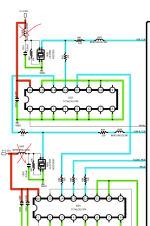
They're there to block the DC offset at the output of the amp, which may be too high for headphones, so I wouldn't bypass them. As you can see they're two back-to-back elcos, which is fine when the DC they're blocking is very low (of the order of mV) or of unknown polarity, but it's a bit of a waste to put two caps in series (which halves the total capacitance) where a single bipolar cap would do. I'd replace them with a single Nichicon ES, which have been shown to have pretty much negligible distortion (here). I'd also go for a larger value, two 220u in series = 110u, which is fine for your high impedance headphones, but if you ever use it with low impedance ones, e.g. the typical 32ohm value, you'd get an F(-3dB) = 45Hz. I'd go with 470u or the highest value that fits in there.should I bypass the caps on the fixed outputs for both L and R channels?
Cheers,
Cabirio
There are many places where you could install the low noise voltage regulators...
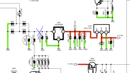
The two red crosses point to where the additional voltage regs (500mA will do plenty) should go... this will only cover the crystal oscillators' clock generation, and their clock signal distribution - a crucial element in any digital audio device.
The blue cross points to where the Vin (for the regulator PCBs) should be sourced from. The voltage drop across the regulators will be substantial, but the current draw is minimal, so all good... (plus, the high voltage drop will ensure a very low noise operation and excellent load regulation). These 2 voltage regs would completely isolate the most important digital section, from everything else that resides on that V+3.301 rail...
Then... that IC99 can also be replaced with a let's say... 2A LDOVR 3.3V LT3045 reg... just make sure that LDOVR voltage regs can work with only 1.7V drop across them...
Then, you can start looking at other voltage regs... those that supply the analog sections.... a sensible electronics engineer should be able to follow the above, I'd hope...
Good luck.
Attachments
@Extreme_Boky
pardon. Should I get the voltage regs from here, like the ones in your initial pic?
https://www.ldovr.com/category-s/113.htm
pardon. Should I get the voltage regs from here, like the ones in your initial pic?
https://www.ldovr.com/category-s/113.htm
For the ones I suggested above in my previous reply (red crosses), get two of these; the voltage should be set by Ldovr to 3.3V (circled in blue below). I also checked the dropout voltage - it is less than 500mV (260mV only ), so they'll do great.
https://www.ldovr.com/product-p/lt3045-0a5g.htm

NOTE: I strongly recommend that you leave this ordering with an engineer who's going to do the actual mods for you... He'll make sure that the voltage regulator PCBs will fit inside that smallish enclosure.
By the way, I obtained really good results when I was burning at least 6-7V across them. This can become a problem if you decide to run 300mA or more through them, but I just realised that Ldovr now provides the heatsinks for them - how cool is that..?

), so they'll do great.https://www.ldovr.com/product-p/lt3045-0a5g.htm
NOTE: I strongly recommend that you leave this ordering with an engineer who's going to do the actual mods for you... He'll make sure that the voltage regulator PCBs will fit inside that smallish enclosure.
By the way, I obtained really good results when I was burning at least 6-7V across them. This can become a problem if you decide to run 300mA or more through them, but I just realised that Ldovr now provides the heatsinks for them - how cool is that..?
Last edited:
I played with many (many)... DACs... for my personal use. They all sounded pretty good; each had its character, pros and cons... and I always struggled with chassis/cases in particular... I could never mount everything I wanted the way I wanted, to look like a ready-made commercial DAC.
One day I realised I was spending tons of money on this DIY DAC stuff... but was not getting the full picture, the completely rounded, good-looking DAC that would do everything I planned/ever wanted in a DAC. So, I ended up with a Holo May DAC.
Amplifiers, on the other hand... are a completely different story. I can make an outstanding amplifier for a fraction of the cost compared to commercial amps; the case can also look pretty good as well. So, yeah... amplifiers can definitely be DIY-ed with great results, at a very reasonable cost.
...and everything can be modified... sometimes just enough to change the sound character to better blend with the rest of a particular system and suit a particular taste; sometimes to improve both the sound and the specifications (like I suggested to you in this thread).
- Home
- Amplifiers
- Headphone Systems
- Can anyone here modify my Marantz HD DAC1 headphone amp?