I don't believe that SOA is a problem, I had a DN2540 that worked at 120C for months with a current of 25mA, the lower mosfet was BSS159, sot23. I currently have one at 140mA in the shunt regulator and I will repeat that not one of them has ever burned out even with higher currents than 140mA and I use them literally everywhere from the amplifier to the regulator.
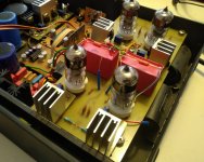
Pictured are four CCS with DN2540 and 2SK3557 as bottom mosfet in my old DAC, they worked for years without any problems. But the picture will say something more, the CCSs themselves are located right next to the tubes without any long wires. The temperature of the heat sinks was around 80C.
There are also better depletion mosfets, such as the IXTP08N50D2, which I recently ordered for a 500mA shunt regulator, and there is no point in using DN2540 as the lower mosfet, better in that position are smaller depletion mosfets, such as; BSS139, BSS159, BSP149, DN1509 or even jfet like 2sk3557 and similar. Using these mosfets or jfets improves the performance of the CCS. More about that here and here.
Attachments
If the FET source does go open circuit, the source's voltage is likely to drift toward B+, as the channel or body-diode leaks current into this ultra high impedance. Meanwhile, the gate will be pulled low by the valve's anode. This is fairly likely to result in the Maximum gate-source voltage of the FET getting violated. (VGSS must be respected both in negative and positive polarity).If the wiper of the trimmer goes open, R approaches ∞, the bottom d-MOSFet won't conduct.
A 9V1 gate-source zener (BZX55C9V1, connected cathode to source) will prevent such a fault; it probably works even better if connected across Drain to Gate resistor (connect cathode to drain, lower FET), as it can also limit SOA transient violations at startup (if these do occur).
A fixed resistor across the trimmer poti is also a good idea; it only needs to be a low enough value to drain away the specified high temperature leakage current - without approaching a 20V drop.
Last edited:
D
Deleted member 548388
Thank you for sharing all the information and experiences!
I guess I'll have to re-think this schematic a bit. What fixed resistor value would be low enough? For now I somehow want to keep using the devices I already have, availability of alternate stuff is too low.
Something else just came to mind: Last time I had a failure, both the 10M90S and the DN2540 were defective. To my understanding, if the 10M90S goes bad (for whatever reason) the bottom device will get fried as well. I know there is a 10M45S available, rated at only 450V. Considering my use-case that would be insufficient by quite a bit. What are the chances that the manufacturer mixed them up and miss-labeled them? What would be an effective procedure to test-bench them outside of the amp of course and prior to being soldered to the PCB?
This is how I test it outside the amp.

After finding out the resistance, I replace the trimpot with a resistor.
Trimpots do fail:
https://gideonlabs.com/categories/potentiometer-failure-analysis/
and trimpots have a limited rotational life.
After finding out the resistance, I replace the trimpot with a resistor.
Trimpots do fail:
https://gideonlabs.com/categories/potentiometer-failure-analysis/
and trimpots have a limited rotational life.
D
Deleted member 548388
I was referring to the 10M90S alone, not the whole CCS.
Sure, pots can fail, but certainly not life-related in this case. They're brand new, adjusted once and kept in the exact same position from then on. After the first failures I even checked the pot to confirm their health.
Sure, pots can fail, but certainly not life-related in this case. They're brand new, adjusted once and kept in the exact same position from then on. After the first failures I even checked the pot to confirm their health.
Breadboard a non-cascode version of CCS, ie single nmos with one resistor and one VR to test 10M90S.
The circuit is in the 10M90S datasheet.
https://www.mouser.com/datasheet/2/240/DS98729A(IXCP-CY10M90S)-1547388.pdf
The circuit is in the 10M90S datasheet.
https://www.mouser.com/datasheet/2/240/DS98729A(IXCP-CY10M90S)-1547388.pdf
I don't remember seeing what your anode supply voltage is.there is a 10M45S available, rated at only 450V. Considering my use-case that would be insufficient by quite a bit.
I would not expect a wrongly marked chip if you bought it from an authorised distributor.
But if it was from Ali or eBay or any other non franchised source, it could happen, or the parts could be outright fakes.
D
Deleted member 548388
DN2540 sometimes burn out at power up, even if the DS voltage below 320..350V. Any spike on HV can cause this.
Theoretically the "upper" FET saves the "lower", but if "upper" damaging, the "lower" go bust too.
In my practice the IXTP-DN pairing was the solution.
The IXTP 01..08N100 and (TO92) DN2540 sacode CCS never broke down -yet- (I use few bunch of them).
Theoretically the "upper" FET saves the "lower", but if "upper" damaging, the "lower" go bust too.
In my practice the IXTP-DN pairing was the solution.
The IXTP 01..08N100 and (TO92) DN2540 sacode CCS never broke down -yet- (I use few bunch of them).
It is really RMS? What is it driving?B+ is about 350V, signal output (R+ vs. R-) exceeds 400V RMS.
D
Deleted member 548388

D
Deleted member 548388
The Stax headphone put high capacitive load between anodes, and there is high peek swings too.
If CCS hasn't enough prevention (no, or too low gate stoppers, long wires, no -few ten...hundred nF- capacitor on B+), possible oscillation occurs -even at MHz region-.
If CCS oscillates, the FETs dissipation (large swing, oscillated current) will growing rapidly, in worst case device would damaging.
D
Deleted member 548388
I guess you're right about everything you stated. Thank you!
That kind of brings us back to my opening post where I expressed my lack of understanding why all of a sudden my (reverse engineered) stuff keeps failing while several hundreds out in the field don't")
I guess the question now is: How do I add proper oscillation protection to this PCB without changing components currently used?
That kind of brings us back to my opening post where I expressed my lack of understanding why all of a sudden my (reverse engineered) stuff keeps failing while several hundreds out in the field don't
I guess the question now is: How do I add proper oscillation protection to this PCB without changing components currently used?
Your CCS should not oscillate as drawn, but there are precautions to be taken in connecting it to the amplifier.
To protect the CCS FETs:
If the CCS curent is only 8-10mA, you can add a 100Ω metal film resistor at the CCS output; this will also improve the stability margin of the CCS.
The 9V1 zener mounted Drain → Gate-resistor I mentioned earlier will protect the lower FET from startup transients, and any kickback from the load.
- It's important to keep the CCS → valve.anode wire short (<75mm for preference), and not too thin (0.6mm Ø).
- The power supply wire should also be short as can be.
- the 10nF PS capacitor shown in the STAX drawing is too small to stabilise a Power FET. I prefer a 100n-470n (type: STACKED MKP) attached to the CCS PCB's input terminal, and a wide ground return. If that is difficult, use a 47µF 400V (ordinary type Panasonic M series; Nichicon VR - not a low ESR type!) electrolytic mounted in the amplifier, and connect to the CCS with 1mm Ø wire - and no film caps. This method leans on the elko ESR to damp out any oscillations.
To protect the CCS FETs:
If the CCS curent is only 8-10mA, you can add a 100Ω metal film resistor at the CCS output; this will also improve the stability margin of the CCS.
The 9V1 zener mounted Drain → Gate-resistor I mentioned earlier will protect the lower FET from startup transients, and any kickback from the load.
- Home
- Amplifiers
- Tubes / Valves
- CCS keeps failing