Your regulator would be best at point of load next to the cap, to minimize inductance. This applies to any fast regulator, and CFP is very fast.
Regulators have an input pin, usually labeled "GND", which is the voltage that the output is referenced to. If it's a discrete reg, that'll be the ground pin of the voltage reference or its filter cap. Using the regulator at point of load means it uses the local ground as reference. So its output voltage is relative to local ground, not relative to "whatever ground is wherever the regulator is". Usually the load prefers its supply voltage to be constant relative to its own local ground, so that's a win.
Having two caps on the same rail, with a long trace between them, is quite often asking for trouble. Or one cap and something which behaves like a low-ESR voltage source. 4 layer PCBs are cheap now, ground and power planes really help.
100nF MLCCs are nice because they're very cheap, low inductance, and they have about 0.1 ohm ESR built-in which could solve your problem. If that's not enough you can add a resistor in series like 1R, over a ground plane it only adds about 1nH (less if you solder it upside down). Thru hole caps have higher inductance, film caps have lower ESR, and both degrade damping, which is undesirable. Bigger thru hole film caps have both higher inductance (due to the size) and even lower ESR...
If your 100nF film caps cause trouble or ringing, I'd recommend replacing them with 100nF MLCC with 0.5R-1R in series. If you have pads for a 5.08mm pin spacing thru hole film cap, you can remove it and solder a 0805 SMD cap and a 0805 resistor in series between the pads, it fits just right.
I'm still struggling with my capacitance multiplier.
Do you measure oscillation at the actual Cap Mx circuit, or are you just concerned, based on the simulation results, that Cap Mx circuit is only marginally stable?
Used models are very detailed and you do account for the PCB tracks inductance. However, adding parasitic capacitances, brings model one step closer to the real circuit. Add “.option cshunt=2e-12”.
My limited experience in comparing calculated phase margin and actual circuit behavior is that there is a difference large enough. As I don’t have a network analyzer to measure actual phase margin, indirect method was used.
There is a relation between transient response under load or Q factor and circuit phase margin. Paper is attached. Practical summary is at the picture nr. 6.
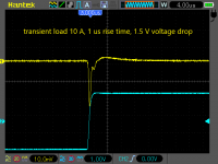
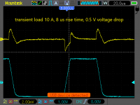
Simple current sink, driven by tone generator, was used to provide square wave load at the power supply output, with desired frequency, load current and rise time. Observing response with oscilloscope, measured phase margin under targeted load conditions was always better than 50°, while Tian probe calculation predicted about 20° margin at best.
Attachments
Hi guys,
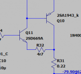
Here is an interesting simulated results in attaching a small degenerators at the driver trannies.To my knowledge the degens was discussed years ago, and I've read that a trade off exist's by losing some loop gain.
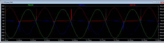
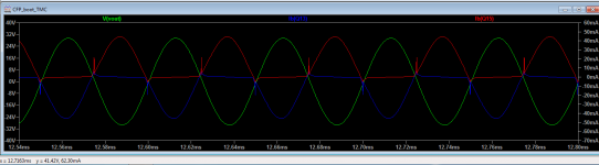
Simulated results executed at 20KHz max power, bias current 25ma per device. The red and blue lines are the output bases and the spike appears at the higher frequencies only, regardless of the output power be it 1W or max power. Topology used TMC + bootstrap + enhanced VAS. Longer spikes 'no degens' shorter spikes 'with degens.'
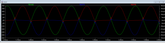
The last graph is 'as built' , an old project of mine using differential VAS with degens (of course 🙂).
(BTW I''m referring to the output stage.)
Here is an interesting simulated results in attaching a small degenerators at the driver trannies.To my knowledge the degens was discussed years ago, and I've read that a trade off exist's by losing some loop gain.
Simulated results executed at 20KHz max power, bias current 25ma per device. The red and blue lines are the output bases and the spike appears at the higher frequencies only, regardless of the output power be it 1W or max power. Topology used TMC + bootstrap + enhanced VAS. Longer spikes 'no degens' shorter spikes 'with degens.'
The last graph is 'as built' , an old project of mine using differential VAS with degens (of course 🙂).
(BTW I''m referring to the output stage.)
Attachments
The CFP is doing well, the problem is the PDN attached. Sorry I phrased this wrong. Any low ESR capacitor at the output makes the CFP go unstable. In my case this is the small decoupling caps I have in parallel to the large high ESR electrolytic cap.Do you measure oscillation at the actual Cap Mx circuit, or are you just concerned, based on the simulation results, that Cap Mx circuit is only marginally stable?
Used models are very detailed and you do account for the PCB tracks inductance. However, adding parasitic capacitances, brings model one step closer to the real circuit. Add “.option cshunt=2e-12”.
My limited experience in comparing calculated phase margin and actual circuit behavior is that there is a difference large enough. [...]
I agree and also have observed that stability in simulation and reality differ significantly from another. Making simulation closer to reality helps.
I have a ground plane that is mostly intact except some deliberate cutouts.Your regulator would be best at point of load next to the cap, to minimize inductance. This applies to any fast regulator, and CFP is very fast.
Regulators have an input pin, usually labeled "GND", which is the voltage that the output is referenced to. If it's a discrete reg, that'll be the ground pin of the voltage reference or its filter cap. Using the regulator at point of load means it uses the local ground as reference. So its output voltage is relative to local ground, not relative to "whatever ground is wherever the regulator is". Usually the load prefers its supply voltage to be constant relative to its own local ground, so that's a win.
Having two caps on the same rail, with a long trace between them, is quite often asking for trouble. Or one cap and something which behaves like a low-ESR voltage source. 4 layer PCBs are cheap now, ground and power planes really help.
100nF MLCCs are nice because they're very cheap, low inductance, and they have about 0.1 ohm ESR built-in which could solve your problem. If that's not enough you can add a resistor in series like 1R, over a ground plane it only adds about 1nH (less if you solder it upside down). Thru hole caps have higher inductance, film caps have lower ESR, and both degrade damping, which is undesirable. Bigger thru hole film caps have both higher inductance (due to the size) and even lower ESR...
If your 100nF film caps cause trouble or ringing, I'd recommend replacing them with 100nF MLCC with 0.5R-1R in series. If you have pads for a 5.08mm pin spacing thru hole film cap, you can remove it and solder a 0805 SMD cap and a 0805 resistor in series between the pads, it fits just right.
I agree, four layer PCBs have become affordable even for DIY use.
When I started the design of this PCB, I had four layers in mind, but then saw opportunity to reduce to two layers.
With power and ground planes there is another capacitor to watch out for: The one resulting from the adjacent planes. This cap is usually pretty small, but very high Q and may resonate with any other high Q cap being part of the PDN.
A 100nF (or any other capacitance in this range) with 100mOhm ESR would be lovely. Can you please let me know a suitable part number?
According to my research, ceramics are closer to 10mOhm ESR unfortunately.
Capacitors with deliberately increased ESR would be perfect.
I did some research and found out that such parts even exist: Look for "controlled ESR" capacitors.
This is a brilliant idea, but those caps are expensive, hard to find and seem available only in low voltage capability.
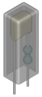
Of course, one can build such parts from just a resistor and capacitor with just a bit more inductance involved.
I even think about your proposal do do this. Both parts potted in a tiny plastic enclosure would be rugged, look nice and professional.
I would sell them for a fortune each as magical audio decoupling capacitors and other than so many audiophool parts they would even do something useful actually.
Hmm you're right, I can't find any at 100mOhms, they're all 30-something. Unfortunately I don't remember how I measured that value, or what caps I used...A 100nF (or any other capacitance in this range) with 100mOhm ESR would be lovely. Can you please let me know a suitable part number?
Anyway, if you want a controlled ESR cap that's in stock, one solution is to use SMD MLCC and SMD chip resistor in series. It increases inductance a little bit, which can be compensated by putting two in parallel. So with 2 caps and 2 resistors, you get about the same inductance as one cap, but you get the ESR too.
- Home
- Amplifiers
- Solid State
- CFP Complementary Feedback Pair - when and how to compensate for stability?