
I think I might start a builder's thread to drum some interest in this design - Mr. Pass, would you mind if I re-posted your schematic there?
Yes please!
I have an idea, the Salas regulator and the SMPS wall-wart are not exclusive. You can get a wall-wart in mouser as high as 48v. How about stacking two Salas shunt regulators one on top of the other to make a virtual ground. I have attached a schematic here. This is untested and hastily drawn. I am thinking of the Salas as an overgrown zener, maybe an abstract diagram would have been better to illustrate the concept.
I have some questions as well:
1) With the output resistor on the j-fets dropped down to 100 ohm is it safe to drive a short? Of course all electrical engineers are perfect so that would never happen in real life") .
.
2) Does this simple jfet follower benefit from very stiff (low impedance) rails or super low noise? Being a follower it should have very good rejection.
3) Has the thinking from Pass Labs about active regulation changed? Most of Nelsons worked used Mosfets in follower mode connected to a voltage reference with no feedback. 6Moons has taken a picture of the guts of the HPA‑1 Headphone Amp and it shows D2081 and D1259 darlington transistors in the regulator stage. It was designed by Jam Somasundram so maybe it just depends on what the designer selects. I suppose in my hart I know the real answer is you have to try each type and see if it makes a difference to you in your particular application.
I have some questions as well:
1) With the output resistor on the j-fets dropped down to 100 ohm is it safe to drive a short? Of course all electrical engineers are perfect so that would never happen in real life
. 2) Does this simple jfet follower benefit from very stiff (low impedance) rails or super low noise? Being a follower it should have very good rejection.
3) Has the thinking from Pass Labs about active regulation changed? Most of Nelsons worked used Mosfets in follower mode connected to a voltage reference with no feedback. 6Moons has taken a picture of the guts of the HPA‑1 Headphone Amp and it shows D2081 and D1259 darlington transistors in the regulator stage. It was designed by Jam Somasundram so maybe it just depends on what the designer selects. I suppose in my hart I know the real answer is you have to try each type and see if it makes a difference to you in your particular application.
Attachments
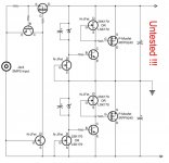
imagine simple positive zenner shunt reg - there is series resistor in rail and zenner itself , as parallel element
for negative , there is series resistor in rail and and zenner itself , as parallel element ;
so , what's missing in your schematic ?
1)pretty much safe even with resistor shorted ; 100R is plentyplenty , anyway
2) yes
3)........ I'm not Pa ....... but- you , as DiY-er - you can always strive for the best** , not good enough for task
**even if not best for overall performance , having better sleep is big enough reason
So let’s flush the question out. The benefits of an SMPS are safety, UL compliance, convenience, isolation of a transformers magnetic field in a remote case, and small size, while the downsides are the need to split rails more complexity, less reliability, more HF noise and less mains isolation (Y1 caps). Mr. Pass has shown us with the ACA and B1 that that a full audio system of good quality can be made with only an SMPS. Can a supply with an SMPS be constructed with the addition of regulation that sounds as good as a low frequency transformer, in order to allow audiophiles to sleep at night without wondering what they are missing?
Logically this should be possible. The PS just provides an imbalance of electrons and we should be able to get clean low impedance DC via filtration and regulation. Hopefully it will not end up becoming too overly complex to justify the exercise (like Uptone Aaudio UltraCap™ LPS-1). You would think that having a higher switching Hz would make it easier to filter, but caps also have parasitic inductance.
I wonder if Mr. Pass put the 10 ohm resistors in there because he feels some filtration is needed in the form of an RC filter or merely to prevent inrush currents from destroying the SMPS?
Rod Elliott has published extensively on SMPS in his article “The Humble Wall Transformer is the Latest Target for Legislators” (he does not appreciate, copying of his work, so I will have to externally link, hope the URL stays put):
Ban On External Transformers
Another problem beside the HF noise are these Y1 caps that bridge the primary and secondary, I wonder if that contributes to subjectively poor quality by injecting mains current and HF garbage. I am not sure how to protect against this. Anybody have any ideas?
My one point of reference is that I built the ACA and it sounds really good. The 6L6 SE has a slight edge on sounds ending in with an ‘s’ with the full range drivers so I prefer it for that reason. But the ACA is actually quieter with deeper base compared to the 6L6. And the ACA is not even cased up.
Zen Mod,
Thank you for your answers.
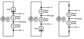
Just one small note, you cannot put another current source on the bottom (if that is what you are suggesting) because there will be a small current imbalance between the two. It’s like trying to put two current sources in series. There is no path back via ground for the extra current. I will attach an abstract set of combinations. Mr. Pass gets away with using resistors because they are kind of like "soft" current sources. You could use resistors in the Salas regulator but the CCS offers higher rejection.
Logically this should be possible. The PS just provides an imbalance of electrons and we should be able to get clean low impedance DC via filtration and regulation. Hopefully it will not end up becoming too overly complex to justify the exercise (like Uptone Aaudio UltraCap™ LPS-1). You would think that having a higher switching Hz would make it easier to filter, but caps also have parasitic inductance.
I wonder if Mr. Pass put the 10 ohm resistors in there because he feels some filtration is needed in the form of an RC filter or merely to prevent inrush currents from destroying the SMPS?
Rod Elliott has published extensively on SMPS in his article “The Humble Wall Transformer is the Latest Target for Legislators” (he does not appreciate, copying of his work, so I will have to externally link, hope the URL stays put):
Ban On External Transformers
Another problem beside the HF noise are these Y1 caps that bridge the primary and secondary, I wonder if that contributes to subjectively poor quality by injecting mains current and HF garbage. I am not sure how to protect against this. Anybody have any ideas?
My one point of reference is that I built the ACA and it sounds really good. The 6L6 SE has a slight edge on sounds ending in with an ‘s’ with the full range drivers so I prefer it for that reason. But the ACA is actually quieter with deeper base compared to the 6L6. And the ACA is not even cased up.
Zen Mod,
Thank you for your answers.
Just one small note, you cannot put another current source on the bottom (if that is what you are suggesting) because there will be a small current imbalance between the two. It’s like trying to put two current sources in series. There is no path back via ground for the extra current. I will attach an abstract set of combinations. Mr. Pass gets away with using resistors because they are kind of like "soft" current sources. You could use resistors in the Salas regulator but the CCS offers higher rejection.
Attachments
Last edited:
I wouldn't use a switcher either. My concern was ....
I might be taking this back.
What a surprise - Mr Pass might be on to something here..
I was experimenting with some high quality SMPS(s).
on the ol' 'scope...
Alone they aren't particularly good, but with a R-C (like NP is suggesting in FW offerings 10 ish ohm/15kuf) before light load, I couldn't see anything below around 200Khz.
With an RF inductor and same C (will measure inductor later when the woofer tester is warmed up), Pretty clean below 50 MHz
neat.
Last edited:
200kHz to 50MHz is a big improvement.
What values are you comparing in the RC and (R+L)C?
I couldn't duplicate my results. Suspect cold temps were affecting equipment. I went back and heated the garage for a bit - much different (worse) results.
There is signature at ~70KHz (which has sub-components in the 50-100 Mhz range) that I was missing. Interesting thing is that there is still a 'shadow' of the signature even with the smps completely unplugged.
It may be that the smps is exacerbating some RF in the area - becoming an antenna and worse when powered.
The LC (2mh / 15kuf -old cheap cap)) eliminates all detectable noise below this ~70 Khz component.
I have RF hunting equip at my disposal and will check it out. might get interesting.
At what frequency do we stop caring ? For the record I've been playing with Vicor FlatPac PSUs - made about 10 miles from here
Looks like their switching frequency increases with increased load. The outputs are isolated as far as I can tell and they seem to series just fine.How did we get here from talking about recommended coupling caps??

Last edited:
70kHz? Could be energy saving light.
This tricked me once to believe I had oscillation in a preamp. Go figure.
Hi Kim,
In your case, was it compact fluorescent lights or LED lighting or something
else?
Thanks,
Dennis
Hi Dennis,
Yes, a fluorescent desk based Magnifying Lamp... The noise spectrum radiated is excessive from the lowest frequencies up to around 2MHz and it's jumping around so it looks like oscillation!
My old apple time capsule on my work bench is radiating noise around 68kHz and my 2010 Apple iMac on my work table is radiating noise up to around 6MHz...
Ghostbusters - Turn on your FFT analysers!
Once my neighbor in the house next to me told me he could tell when I turned my computer on in the morning. It seems my computer was sending out so much RF I was killing his AM radio ! I opened the computer power supply and found that a couple places in thepower line filter for caps just didn't have caps installed. Well any way to save a couple of cents !
Sorry about that. I did wonder why the product seemed stale in
the marketplace...
Here's the schematic.
A couple queries regarding this :
- without the input potentiometer P101 , is the input impedance is 1M ohms here .
- as we have pot P102 here do the fets needs to be matched? Or we can adjust the pot and use unmatched fets..
The B1 input is a jFET. That has a very high input impedance.
The capacitance of the jFET will give an impedance that falls as frequency goes up, but even at the top of the audio band, it is still well over 100kohms.
If other resistors are added to the input, then they determine the final input impedance.
The B1 uses a single jFET as the amplifier (with gain set to 1times since it is a Unity Gain Follower) and this is loaded with a Constant Current Sink (CCS).
The design of the B1 requires that the two jFETs pass identical currents. This is enabled by you selecting equal Idss for both devices.
If you select different Idss, then one device will operate at Idss and the other will operate at Id. This is not optimal, particularly if Id ends up being higher than it's Idss.
Read D.Feucht.
Attachments
Last edited:
With regards to output caps of the original B1 design, I was unable to source the AEON that Nelson Pass used here in the UK. I used Mundorf MKP 10uF 250V instead.
I was not completely satisfied with the result in the end though. I think, when PP caps get too big they really don't sound great in some respects such as glare, timbre and transient handling.
I had some Cornell-Dubilier 940C Polypropylene Film Capacitors, 3kV, 10nF lying around and I bypassed both the input and output caps with these. They are not expensive (around $3-4 each) as they are not intended for audio.
I am very pleased with the result: gone is the glare and transient response and timbre are much improved. This is a really superb preamp!
Also, I use a TKD 50KOhm pot in my build which I also highly recommend.
- Home
- Amplifiers
- Pass Labs
- Choosing best output coupling capacitors for B1