There's nothing at all special about the Kicker, in fact it's quite unimpressive in all respects. This was the silver cone era for the L7s and qts was 0.666. Not at all special in any way, actually quite unremarkable. Definitely not worth the price Kicker charged.
Kicker won the game and was able to command high prices for one reason only, the box design. When you stick a high q driver in a very undersized ported box you get a massive peak. It sounds terrible (not musical) but it wins comps and sells drivers. The designs are super simple and anyone can make them so you had a generation of dummies driving around in Kicker burpmobiles that sounded terrible when playing actual music.
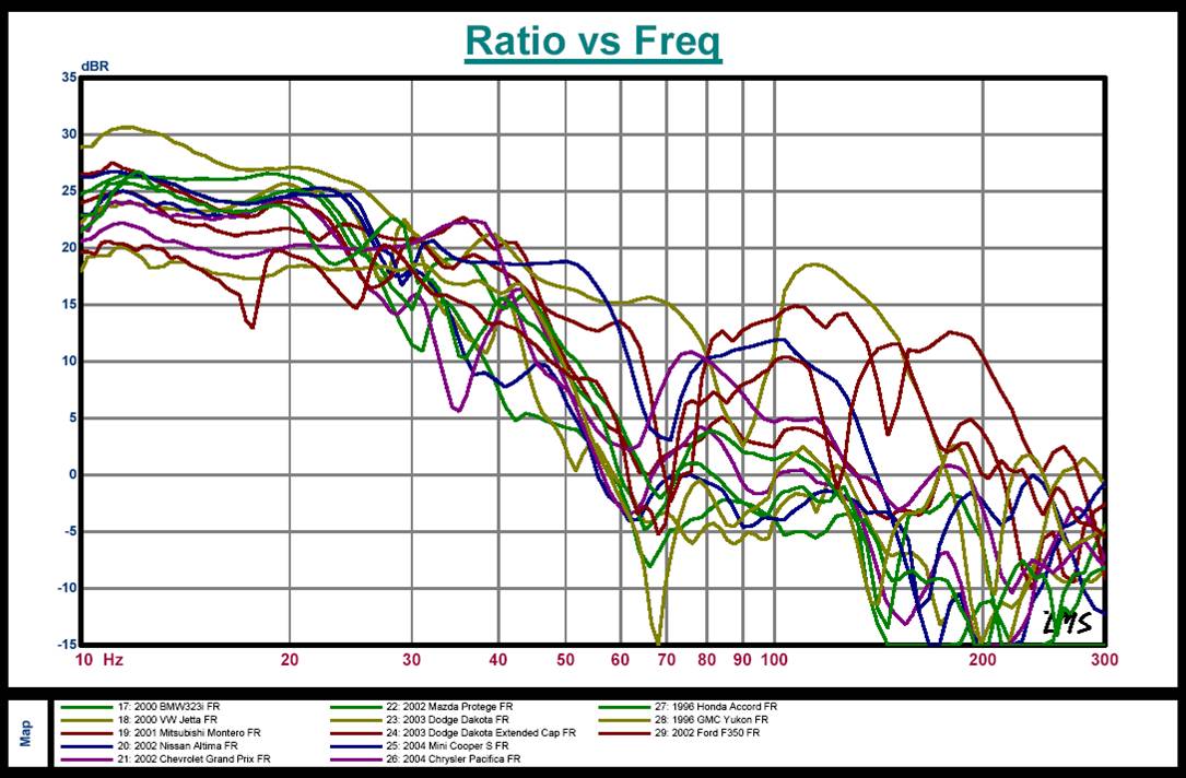
There's a bit of "theory" behind the use of high-Q drivers in car audio like that. Imagine what the response would look like with the average 12dB/oct lift below 80 Hz or so that you can get in-car...
JBL produced a series of high-Q car audio subwoofers (the MS series) with this in mind. Modelled, the drivers would exhibit a peak at 80 Hz and a rolloff below that. Factor in the cabin gain, and the output gets a lot smoother at low frequencies.
Sure, but the sim I showed rolls off way too steep to flatten out from cabin gain. I'm pretty sure the max cabin gain you can get is 12 db/oct and I don't think you can always count of the full 12 db.
There's usually also a peak at the car's resonant frequency which will peak that peaky response even more.
I'm all for measuring cabin gain and making your sub have the inverse curve so it plays flat with no eq but the sim I showed is just too extreme to end up flat.
Anyway, measuring is essential since this pic shows that cabin gain could be just about anything - sometimes not nearly 12 db/oct, sometimes bumpier than the road.
Kicker and shtuff
Just a Guy and Brian Steele,
That is interesting history about Kicker and their SPL cabs , and the reasoning behind producing their drivers with a high Qts parameter.....🙂
That chart showing the various vehicle model's cabin gain responses is also very cool .... So much variance between them!
P.S.
I have noticed that car audio guys choose to make Kicker brand the "butt" of so many jokes ...... Hehe .... Is that a recent trend or am I just now noticing it since i am becoming friends with more car audio folks on social networking? I don't know ........ Seems like they could have chosen some lesser brand to be the focus of their ridicule, you know, like "Boss" or "Dual" or something along those lines😛 ....
P.P.S.
How about that new "Lossy Le" function in Hornresp? .... When do you guys suppose it is appropriate to use that option? Isn't the inductance in voicecoils of a lossy nature in general? I have seen some of Brian's sims match up perfectly with his real-world results without using that feature so i would have to assume that the "Lossy Le" feature should not be enabled in sim for the driver he used ..
P.P.P.S.
More Super Planar stuff coming up ... For fun I put together a comparison involving multiple MCM 2421s in FLH horns vs a Super Planar cabinet...Not that i would build either loaded with a bunch of 2421s but interesting results nonetheless...
Last edited:
Just a Guy and Brian Steele,
That is interesting history about Kicker and their SPL cabs , and the reasoning behind producing their drivers with a high Qts parameter.....🙂
The newer kickers have a lower qts but still not anywhere near the prices they ask for them.
P.S.
I have noticed that car audio guys choose to make Kicker brand the "butt" of so many jokes ...... Hehe .... Is that a recent trend or am I just now noticing it since i am becoming friends with more car audio folks on social networking? I don't know ........ Seems like they could have chosen some lesser brand to be the focus of their ridicule, you know, like "Boss" or "Dual" or something along those lines😛 ....
I don't hang out in the car audio forums but I'm not surprised. Kicker was a big name back in the day and with the advent of the newer modern long stroke drivers (which are also basically high qts when lossy inductance is factored in) it's become more clear how unimpressive the Kicker drivers actually are. For Kicker the fame came from those peaky box designs. Now anybody with a few hundred dollars can get a much better driver and whup the Kickers all over the place.
P.P.S.
How about that "Lossy Le" function in Hornresp? .... When do you guys suppose it is appropriate to use that option? Isn't the inductance in voicecoils of a lossy nature in general? I have seen some of Brian's sims match up perfectly with his real-world results without using that feature so i would have to assume that the "Lossy Le" feature should not be enabled in sim for the driver he used ..
If you want you can read the paper I wrote to accompany the Lossy Le feature (I've learned a lot since then too though), it's here - Large Coil Simulation Accuracy Issue And Adjustment - amateur audio
Basically it's the long stroke drivers with lots of metal around the coil that are influenced most by lossy inductance losses. Those are the only ones I studied. Pro drivers don't have too much issues with lossy inductance losses.
Ricci has commented in the Hornresp thread that all drivers benefit from using Lossy Le in the sim, even tweeters. He says the measured results will come in between the Lossy Le model and a normal model but closer to the Lossy Le model. I don't have time to look up his quotes now but he was doing similar tweaking to his sims LONG before I ever did my lossy inductance study as he noticed that sims didn't match measurements for certain drivers, which incidentally is the same reason I embarked on my own study which was peer reviewed (and the peers helped a good bit) and subsequently included in Hornresp.
FWIW the Lossy Le adjustment is not a perfect tool but it's a whole lot better than ignoring the issue.
Thank you Mathew Morgan
I don't know of any GKH.
Having read this thread, you should. 😀
Excellent!
Just A Guy , i just read your entire paper and looked at all of the graphs/charts and this is some great stuff!! Thank you for this!
So generally speaking what You and the peers have observed is a trend of motor force losses that must be compensated for in order to have accurate simulations when drivers with high voicecoil Inductance (Le) to voicecoil resistance (Re) ratios are involved, correct?
You used Le/Re in your list .... The reduction in BL required to get accurate simulations was in the range of -20% to -35% .... The higher Le/Re figures correlated on average with increased loss of motor force in the real world...............
This is some smart and useful stuff that you guys have put together here!
I can say for sure now that when simulating our RS 8 driver (as was used in Mr Vansickle's 50hz Super Planar 8th) the "Lossy Le" option will need to be enabled for the sake of accuracy ....... Same with an American Bass 15 that i recently modeled .. .
Hmmm ... So the moral of the story here if i understand correctly is that the BL^2/Re doesn't tell us everything we need to know about motor force.... The incredibly high Le to Re ratio on some of these large coiled subs renders them less impressive despite their high BL^2/Re figures ............ I noticed something similar to this a while ago when increasing the Le figure in Hornresp simulations (before you guys added the proper "Lossy Le" option) but now i can see that the new option behaves differently than just raising the Le in sim .. .
Ok , So , Just A Guy, I have a question about how this is set up in Hornesp:
Does the "Lossy Le" option in Hornresp calculate/estimate the appropriate amount of reduction in BL required based upon the particular driver's Le/Re ratio?? Or did David just go with an average figure of 70%-ish of initial BL when the option is enabled?
....
If you want you can read the paper I wrote to accompany the Lossy Le feature (I've learned a lot since then too though), it's here - Large Coil Simulation Accuracy Issue And Adjustment - amateur audio
Basically it's the long stroke drivers with lots of metal around the coil that are influenced most by lossy inductance losses. Those are the only ones I studied. Pro drivers don't have too much issues with lossy inductance losses.
Ricci has commented in the Hornresp thread that all drivers benefit from using Lossy Le in the sim, even tweeters. He says the measured results will come in between the Lossy Le model and a normal model but closer to the Lossy Le model. I don't have time to look up his quotes now but he was doing similar tweaking to his sims LONG before I ever did my lossy inductance study as he noticed that sims didn't match measurements for certain drivers, which incidentally is the same reason I embarked on my own study which was peer reviewed (and the peers helped a good bit) and subsequently included in Hornresp.
FWIW the Lossy Le adjustment is not a perfect tool but it's a whole lot better than ignoring the issue.
Just A Guy , i just read your entire paper and looked at all of the graphs/charts and this is some great stuff!!
Thank you for this! So generally speaking what You and the peers have observed is a trend of motor force losses that must be compensated for in order to have accurate simulations when drivers with high voicecoil Inductance (Le) to voicecoil resistance (Re) ratios are involved, correct?
You used Le/Re in your list .... The reduction in BL required to get accurate simulations was in the range of -20% to -35% .... The higher Le/Re figures correlated on average with increased loss of motor force in the real world...............
This is some smart and useful stuff that you guys have put together here!
I can say for sure now that when simulating our RS 8 driver (as was used in Mr Vansickle's 50hz Super Planar 8th) the "Lossy Le" option will need to be enabled for the sake of accuracy ....... Same with an American Bass 15 that i recently modeled .. .
Hmmm ... So the moral of the story here if i understand correctly is that the BL^2/Re doesn't tell us everything we need to know about motor force.... The incredibly high Le to Re ratio on some of these large coiled subs renders them less impressive despite their high BL^2/Re figures ............ I noticed something similar to this a while ago when increasing the Le figure in Hornresp simulations (before you guys added the proper "Lossy Le" option) but now i can see that the new option behaves differently than just raising the Le in sim .. .
Ok , So , Just A Guy, I have a question about how this is set up in Hornesp:
Does the "Lossy Le" option in Hornresp calculate/estimate the appropriate amount of reduction in BL required based upon the particular driver's Le/Re ratio?? Or did David just go with an average figure of 70%-ish of initial BL when the option is enabled?
....
Major!
Gkh ,
You are a major contributor!
How are things going on your end Gerald? Time to make sawdust yet?😉
Having read this thread, you should. 😀
Gkh ,
You are a major contributor!
How are things going on your end Gerald? Time to make sawdust yet?😉
Sure, but the sim I showed rolls off way too steep to flatten out from cabin gain. I'm pretty sure the max cabin gain you can get is 12 db/oct and I don't think you can always count of the full 12 db.
With a 41Hz Fb, suggesting that the purpose of this box is for SPL use, yes, the rolloff below Fb will be too steep. However, drop Fb to 32 Hz, and then you'll get a response rolloff that's pretty close to 12dB/octave, all the way down to 20 Hz.
Of course, no car has a perfect 12dB/octave increase in cabin gain. There will always be peaks and dips in the response. But taking an average cabin gain of 12dB/octave into consideration in the design does get you closer to a good response in-car compared to not taking it into consideration at all.
Attachments


I have seen some of Brian's sims match up perfectly with his real-world results without using that feature so i would have to assume that the "Lossy Le" feature should not be enabled in sim for the driver he used ..
That's probably because I avoid using high Le drivers in general 🙂
Seriously, JAG's put a lot of work into the Lossy Le model. There seems to be good correlation between sims and measurements, which would probably even better if you consider all of the factors that can influence FR measurements, including the power level used.
As for my sims matching up "perfectly", there are a close match, but not perfect, and I suspect that the difference is due to box losses, which are not covered by HornResp. I've been having a look at trying to emulate said losses by including the impact of light stuffing (Fr>=2) in the sim, and the results look promising, and there's also closer correlation between the sim'd impedance curve and the measured one, but there really isn't much data to work with yet to say this "ratch" is a good one to use.
Just A Guy , i just read your entire paper and looked at all of the graphs/charts and this is some great stuff!!
So generally speaking what You and the peers have observed is a trend of motor force losses that must be compensated for in order to have accurate simulations when drivers with high voicecoil Inductance (Le) to voicecoil resistance (Re) ratios are involved, correct?
Yes, I realized that measurements on data-bass did not match sims, and I knew how to "fix" the sims immediately since I recognized the curve shape and knew it was the same as when you add Re to a sim to crudely simulate power compression. Ricci noticed sims didn't match measurements years before I did and he had his own methods of making the sims match better but he didn't have a "one size fits all" adjustment and he didn't talk about the issue much on the forums.
My "peers" (if I can call them that) saw my early work and found enough value in it to push it along to the final stage, both LTD02 and David McBean were very helpful.
You used Le/Re in your list .... The reduction in BL required to get accurate simulations was in the range of -20% to -35% .... The higher Le/Re figures correlated on average with increased loss of motor force in the real world...............
This is some smart and useful stuff that you guys have put together here!
If you want to see the REAL smart work, look into Leach's paper on lossy inductance. He covers it MUCH better than I did, he mathematically quantified it and made new complex inductance t/s parameters to "fix" the sim. The problem is that no manufacturer publishes these complex inductance parameters so you have to measure yourself, and the only simulator I know of that will accept these parameters is Unibox. So I was forced to make my own adjustment.
Hmmm ... So the moral of the story here if i understand correctly is that the BL^2/Re doesn't tell us everything we need to know about motor force.... The incredibly high Le to Re ratio on some of these large coiled subs renders them less impressive despite their high BL^2/Re figures ............ I noticed something similar to this a while ago when increasing the Le figure in Hornresp simulations (before you guys added the proper "Lossy Le" option) but now i can see that the new option behaves differently than just raising the Le in sim .. .
Yes, and even the bottom of the barrel long stroke drivers were affected. The Dayton driver in the study only had 14 mm xmax IIRC and it benefited from the adjustment. However it required very little adjustment compared to some others.
Ok , So , Just A Guy, I have a question about how this is set up in Hornesp:
Does the "Lossy Le" option in Hornresp calculate/estimate the appropriate amount of reduction in BL required based upon the particular driver's Le/Re ratio?? Or did David just go with an average figure of 70%-ish of initial BL when the option is enabled?
....
Hornresp uses the formula in the paper, the formula is located right after the scatter charts in the paper IIRC. It's not an average figure, Hornresp actually calculates the formula and adjusts based on the Le/Re ratio.
That formula can also be used independently of Hornresp, you can run the numbers and apply the adjustment and enter the t/s into any simulator of your choice.
If you have the Lossy Le tool on in the main window of Hornresp and hover your mouse over the Bl input box, at the bottom of the Hornresp window it will tell you the new calculated value for Bl. That's everything you need to know, since the adjustment only affects Bl.
Gkh ,
You are a major contributor!
How are things going on your end Gerald? Time to make sawdust yet?😉
Thanks, MMJ!🙂
No sawdust yet - the Oberton drivers were not delivered; and for the bigger projects I still need a workshop. 😡
Losses and albatrosses
Brian,
I can see now why that would be a good policy, considering these correlations between Le:Re and BL ....
I suppose only if the driver had plenty of surplus BL^2/Re to begin with (and a low-ish Qes) it means that a high Le:Re ratio could potentially work out alright in the end after BL is adjusted down to emulate the losses ...
I can also see how the combination of high Qts and high Le is especially undesirable .... Unfortunately that combination is tragically common in car audio subwoofers. 🙁
I guess it will help to "separate the wheat from the chaff" as they say ....... Some drivers that used to appear competitive really aren't as it turns out . .... There are a few that i wish i wouldn't have added to the list of appropriate drivers for certain designs of the past ..
Brian, Yours are getting very close , you are really down to splitting hairs now .... I suspect you might have some perfectionist tendencies 😉...
That's probably because I avoid using high Le drivers in general 🙂
Brian,
I can see now why that would be a good policy, considering these correlations between Le:Re and BL ....
I suppose only if the driver had plenty of surplus BL^2/Re to begin with (and a low-ish Qes) it means that a high Le:Re ratio could potentially work out alright in the end after BL is adjusted down to emulate the losses ...
I can also see how the combination of high Qts and high Le is especially undesirable .... Unfortunately that combination is tragically common in car audio subwoofers. 🙁
Seriously, JAG's put a lot of work into the Lossy Le model. There seems to be good correlation between sims and measurements, which would probably even better if you consider all of the factors that can influence FR measurements, including the power level used.
I guess it will help to "separate the wheat from the chaff" as they say ....... Some drivers that used to appear competitive really aren't as it turns out .
.... There are a few that i wish i wouldn't have added to the list of appropriate drivers for certain designs of the past .. As for my sims matching up "perfectly", there are a close match, but not perfect, and I suspect that the difference is due to box losses, which are not covered by HornResp. .
Brian, Yours are getting very close
, you are really down to splitting hairs now .... I suspect you might have some perfectionist tendencies 😉...A few questions and comments ..
Just a Guy,
Ok, So i have a question then ..... Since many of the drivers that you based the formula upon are very long excursion drivers does it mean that the formula may overcompensate for drivers with less excursion despite their high Le to Re values? Or does it matter? .....
In other words: should i still use the "Lossy Le" option if i am working with a car audio style sub driver that only has 10mm of linear one-way cone travel?
I shouldn't have asked so soon because I was able to spot it quickly enough when i had a look at the very small reduction made to the BL of the 15LB100 (has a very low Le relative to Re) when enabling the "Lossy Le" option as opposed to the massive compensation observed with something like an American Bass brand sub , or SoundQubed sub, Sundown, etc etc ...
That is a cool feature ... Now we can easily see what the effective BL is🙂....
After the formula is applied can we call the adjusted BL our "Effective BL"? Seems appropriate ..
Yes, and even the bottom of the barrel long stroke drivers were affected. The Dayton driver in the study only had 14 mm xmax IIRC and it benefited from the adjustment. However it required very little adjustment compared to some others.
Just a Guy,
Ok, So i have a question then ..... Since many of the drivers that you based the formula upon are very long excursion drivers does it mean that the formula may overcompensate for drivers with less excursion despite their high Le to Re values? Or does it matter? .....
In other words: should i still use the "Lossy Le" option if i am working with a car audio style sub driver that only has 10mm of linear one-way cone travel?
Hornresp uses the formula in the paper, the formula is located right after the scatter charts in the paper IIRC. It's not an average figure, Hornresp actually calculates the formula and adjusts based on the Le/Re ratio.
I shouldn't have asked so soon because I was able to spot it quickly enough when i had a look at the very small reduction made to the BL of the 15LB100 (has a very low Le relative to Re) when enabling the "Lossy Le" option as opposed to the massive compensation observed with something like an American Bass brand sub , or SoundQubed sub, Sundown, etc etc ...
If you have the Lossy Le tool on in the main window of Hornresp and hover your mouse over the Bl input box, at the bottom of the Hornresp window it will tell you the new calculated value for Bl. That's everything you need to know, since the adjustment only affects Bl.
That is a cool feature ... Now we can easily see what the effective BL is🙂....
After the formula is applied can we call the adjusted BL our "Effective BL"? Seems appropriate ..
The difference is astounding
The difference between published motor force and effective motor force..
Our subject is the Massive Audio brand HIPPO 122
PUBLISHED MOTOR FORCE
(BL calculated from Qes and other published parameters)
BL^2/Re = 207.94 motor force figure
EFFECTIVE MOTOR FORCE
(compensated BL via "Lossy Le option)
BL^2/Re = 94.66 motor force figure
The above driver in our example loses more than half of it's motor force to the lossy inductance!!😱
Silver lining
Gerald,
I am really saddened to hear about the Oberton deal not working out, that would have been such an extraordinary value ..... Maybe we can find a decent alternative though ...
About the workshop, maybe it is ok that you haven't found one just yet because we continue to find better ways to refine these ideas and designs!
Thanks, MMJ!🙂
No sawdust yet - the Oberton drivers were not delivered; and for the bigger projects I still need a workshop. 😡
Gerald,
I am really saddened to hear about the Oberton deal not working out, that would have been such an extraordinary value ..... Maybe we can find a decent alternative though ...
About the workshop, maybe it is ok that you haven't found one just yet because we continue to find better ways to refine these ideas and designs!
Just a Guy,
Ok, So i have a question then ..... Since many of the drivers that you based the formula upon are very long excursion drivers does it mean that the formula may overcompensate for drivers with less excursion despite their high Le to Re values? Or does it matter? .....
Look at the scatter chart in the paper. Very few of the drivers hit right on the line for the formula - as the term scatter implies, the data is scattered all over the place. Every driver is different, a generic formula like this absolutely cannot be perfect, it will overshoot on certain drivers and it will undershoot on certain drivers. A few drivers will land right on the mark, as you can see by the website download page graphic of the Mach 5 UXL, that driver is a really nice fit.
A generic formula like this will never be perfect, and a solution as simple as adjusting a single t/s parameter to quantify the issue will also never be perfect. If you look at Leach's paper on lossy inductance you will see how much math goes into quantifying the issue properly. David McBean was not interested in going to all the work required to integrate a more complete method like Leach's or Wright's but my solution was simple enough to incorporate pretty easily and the results produced were good enough to go to the bother. But let's be really clear - this is not a super accurate way to quantify the issue. It's pretty good but it's far from perfect.
If you want to get more accurate it is possible, just use the method I did to generate the generic formula but apply it on a driver by driver basis. Take a driver, put it in a sealed box, measure it and simulate the sealed box it's in (along with measured driver t/s). Then adjust Bl until the sim matches the measurement. Then use that value of Bl in all subsequent sims.
Then you are not using the generic formula which can overshoot or undershoot. You have the exactly Bl value that makes the sim match the measurement. This method takes a little more work, you have to have the driver in hand, you need to make a sealed box for it and you have to measure it (actually that's a lot more work) but then you are guaranteed to have the Bl value that makes the sim match the measurement. This still won't be perfect because you are only adjusting a single parameter (Bl) to estimate the effect of a complex behavior (lossy inductance) but as I've shown, even with the generic formula the results are a lot better than just ignoring the issue.
In other words: should i still use the "Lossy Le" option if i am working with a car audio style sub driver that only has 10mm of linear one-way cone travel?
Hard to say. Does it look like a beefy motor with lots of steel around the coil? How long is the coil? All I can really tell you is that it's a judgement call in this case and if you sim it both ways (with and without the Lossy Le feature) the measured results will fall somewhere in between the with and without sims.
After the formula is applied can we call the adjusted BL our "Effective BL"? Seems appropriate ..
I suppose so, sure. I've been saying "apparent motor strength" to comment on the difference between the measured apparent motor strength vs what the t/s would suggest in a simple sim.
The difference between published motor force and effective motor force..
Our subject is the Massive Audio brand HIPPO 122
PUBLISHED MOTOR FORCE
(BL calculated from Qes and other published parameters)
BL^2/Re = 207.94 motor force figure
EFFECTIVE MOTOR FORCE
(compensated BL via "Lossy Le option)
BL^2/Re = 94.66 motor force figure
The above driver in our example loses more than half of it's motor force to the lossy inductance!!😱
Can you post the t/s? I couldn't find much in a quick search.
Sure thing
Just A Guy ,
Here is a link to the manual
I don't own the driver (and i am not trying to design anything for it) , i was just using it as an example . .
Can you post the t/s? I couldn't find much in a quick search.
Just A Guy ,
Here is a link to the manual
I don't own the driver (and i am not trying to design anything for it) , i was just using it as an example . .
A few more charts for your viewing pleasure
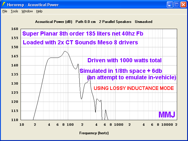
Here is what a couple of CT Sounds Meso 8 drivers look like in a 40hz tuned Super Planar 8th order cabinet .... This is in 1/8th space+6db which was just an attempt to roughly approximate in-vehicle response and output (but in reality the response curve's shape will be somewhat altered by the influence of the vehicle's cabin) ..
NOTE: You can see that it says "2 Parallel Speakers" above the chart .... This is how we managed to gain the +6db above 1/8th space .. ..
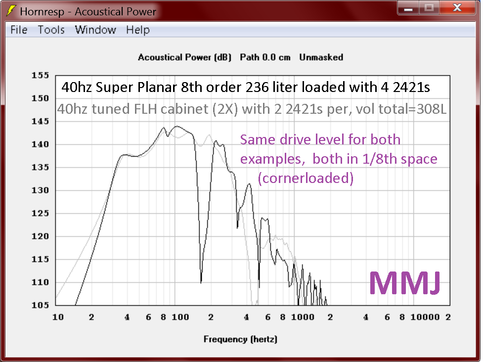
I also modeled multiple MCM 55-2421 drivers in Front-Loaded-Horns and also a Super Planar 8th order cabinet, not that i would build one with a quad of 2421s , no, it was just for fun and to satisfy my curiosity.. ............... The 2421's parameters are extremely well suited for FLH designs but the Super Planar keeps right up in terms of output yet with much less internal volume required! 😀
Here is what a couple of CT Sounds Meso 8 drivers look like in a 40hz tuned Super Planar 8th order cabinet .... This is in 1/8th space+6db which was just an attempt to roughly approximate in-vehicle response and output (but in reality the response curve's shape will be somewhat altered by the influence of the vehicle's cabin) ..
NOTE: You can see that it says "2 Parallel Speakers" above the chart .... This is how we managed to gain the +6db above 1/8th space .. ..
I also modeled multiple MCM 55-2421 drivers in Front-Loaded-Horns and also a Super Planar 8th order cabinet, not that i would build one with a quad of 2421s , no, it was just for fun and to satisfy my curiosity.. ............... The 2421's parameters are extremely well suited for FLH designs but the Super Planar keeps right up in terms of output yet with much less internal volume required! 😀
Last edited:
- Home
- Loudspeakers
- Subwoofers
- Compound loading 6th order quarterwave "Super Planar" horns and pipes concepts/builds