I built a LM338 board that also has the ccs option. I only tested it at 100mA out but I plan on testing it at around 4.5A.
At 100mA the PSRR at 100Hz is at around -138dB. Noise level seems to be around 645pV/√Hz (without LNA's noise). I used ZTX851/BC327 for the dienoiser and BC327 for the CCS. Needs a regular 5mm red led. The dienoiser current was set at around 9mA, with around 3-4mA through the LED. Increasing the dienoiser current makes for worse results, the LM338 doesn't seem to like more. 120R seems like a good value.
Compensation was 47n/1R. Output cap I used Elna RJH 120uF/35V, just because I had it and measured around 0.2R for impedance.
The board is to be used with DC input only. This way, especially for higher output current, you can have a separate rectification/filtering board. Board size is about 48mm x 35mm. Can be diyed.
I'll post measurements after I get to test it at 4.5Aout.
edit: voltage setting resistors are 0805 footprint, compensation network as well.
I did ltsimulation of this circuit at 40mA but result was not that good. Can you share yours if you have any?
A PSRR of >130dB is not to be scuffed at, IMHO.
The denoiser family addresses 3 issues: noise, PSRR and output impedance, and they are all improved by the same factor.
If only PSRR bothers you, you can use a cap multiplier in front of a 317, it will give you ~60dB improvement, against ~30dB for the simple denoiser.
Die- and no-noiser are better though, and none of these improvements require additional voltage headroom, unlike a cap-mult
I couldn't find any official spice model for LM338. But you can test with with LM317. You can get the model here: https://www.ti.com/lit/zip/snvmap2
Attachments
For lower output voltage like 5V the CCS version shouldn't be used. At first look the Nazar version seems to hold a higher PSRR at lower output voltage. But you'd have to confirm this by testing it. Its noise could also be lowered I think depending on the BJTs you use, as far as simulation shows.
DieNoiser Simulation Parameters
Hi, i have simulated DieNoiser and it shows very nice parameters from simulation, and startup time is very fast. So i have question what is replacement for BC327-25 (mouser does not have from OnSemi or STMicroelectronics manufacturer), and if remote sense are wired correctly on schematic?And will RCRC improve regulator PSRR at input or is not needed because regulator will give that nice PSSR as in simulation?
What i got from simulation is very nice result:
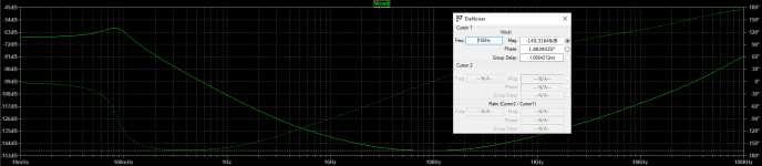
PSRR: -149dB@100Hz
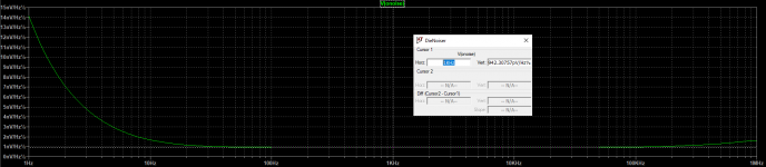
Output Noise: 0,95nV/Hz@1kHz
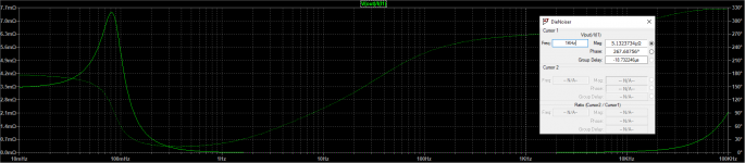
Output Impendance: 5,13uohm@1kHz
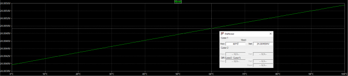
Temperature Stability: 24,004934V@60°C
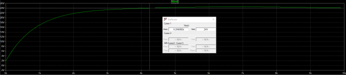
Startup: 4,24sec to get to full output voltage (24VDC@100mA load)
Hi, i have simulated DieNoiser and it shows very nice parameters from simulation, and startup time is very fast. So i have question what is replacement for BC327-25 (mouser does not have from OnSemi or STMicroelectronics manufacturer), and if remote sense are wired correctly on schematic?And will RCRC improve regulator PSRR at input or is not needed because regulator will give that nice PSSR as in simulation?
What i got from simulation is very nice result:
PSRR: -149dB@100Hz
Output Noise: 0,95nV/Hz@1kHz
Output Impendance: 5,13uohm@1kHz
Temperature Stability: 24,004934V@60°C
Startup: 4,24sec to get to full output voltage (24VDC@100mA load)
Attachments
-
 Dienoiser - StartUp.png20 KB · Views: 213
 -
 Dienoiser - Noise.png40.4 KB · Views: 698
 -
 Dienoiser - PSRR.png48.3 KB · Views: 696
 -
 Dienoiser - Output Impendance.png48 KB · Views: 693
 -
 Dienoiser - Temperature Stabilitz.png20.9 KB · Views: 771
 -
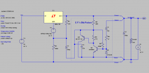 Dienoiser - Schematic.png54.7 KB · Views: 839
 -
ZTX851.txt408 bytes · Views: 74
-
DieNoiser.asc3.9 KB · Views: 80
You can use a 2N4401, S9013, S8050, etc. Any medium-current, GP type will do.
If you are after the ultimate noise performance, use a ZTX--- type, they have the lowest Rbb possible.
Your 4-wire connection is drawn correctly.
The actual performances won't match the sim, but they will be close. If you think you need better than 130~140dB PSRR, you can always add a CRC
If you are after the ultimate noise performance, use a ZTX--- type, they have the lowest Rbb possible.
Your 4-wire connection is drawn correctly.
The actual performances won't match the sim, but they will be close. If you think you need better than 130~140dB PSRR, you can always add a CRC
So i have question what is replacement for BC327-25 ..
The gain selection of the transistor is mostly indifferent: -16, -25, -40 or unselected types will work equally well.
The denoiser's performance is dictated by the transconductance, which does not depend on the gain, except that a higher gain type will bias itself at a slightly larger current, but this effect is compensated by the higher Hoe of higher beta transistors: the Early voltage is inversely correlated to the beta, for a given process.
No need to worry. Mouser has BC327-40 in stock.
Noise level will be as calculated by simulation but PSRR is a little bit optimistic. Real circuit will easily have 130 -135 dB PSRR or slightly more with good design, components and tweaks. But, one must ask himself does he really need more and for what reason. There are more than enough proven and measured designs in this thread to choose from. No need to design new one from the scratch, except if it is for learning.
Edit:
Hah, of course Elvee replied while I was typing.
")
If you think you need better than 130~140dB PSRR, you can always add a CRC
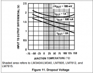
Or an LM78xx 3-pin voltage regulator IC before the LM317. This will reduce 50 Hz - 120 Hz mains hum by an additional 60dB to 70 dB, at the cost of 1.5 to 2 volts of headroom.
_
Attachments
Updated Schematic With Snubbler+Rectifier+RCRC+Dienoiser
I updated schematic to get output 24VDC and heatsink is SK129 6.5C/W so that LM317 will be cold.
I would like to push Dienoiser to it's maximum so:
- added RCRC filter and from simulation i got -172dB PSRR (so we pushed PSRR at their maximum).
- ZTX851/951 was choosen for Q1 and Q2 to get the lowest noise possible (below 1nV/Hz)
- added two LM317 and use of dual secondary toroid to get output of +/-24VDC (because LM337 is not good as LM317), LM317 is connected in series - like battery to archieve +/- output voltage at same parameters.
QUESTION:
- can we have remote sense with kelvin sensing? This way Kelvin sensing will be sensing output connector on PCB where we connect wires for V+ GND and V-, and remote connectors in + and - side with 10R resistor will be sensing on preamp and compensate long wires and make the voltage at remote preamp stable. If we can add remote sense could you draw in paint where need to go where wires for remote sense connectors?
- on LM317 i see that many schemes have 1N4007 diode between IN and OUT of LM317 for extra protection...should i added it to schematic and does it will ruin performance? (Zout?)
- 5k potentiometer is connected to VGND, is it better to add bettween potentiometer and VGND a resistor, say for example 47R?
- do we need to add current limiter before IN of LM317? I ask this if we power up first time preamp and there is something in short, preamp will pull more that 1A and LM317 does not have current limiter, so it will get very hot and shutdown....so adding current limiter make sense or not?
Thanks.
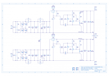
Here is schematic that i im preparing for PCB Layout when i got all questions answered.

I updated schematic to get output 24VDC and heatsink is SK129 6.5C/W so that LM317 will be cold.
I would like to push Dienoiser to it's maximum so:
- added RCRC filter and from simulation i got -172dB PSRR (so we pushed PSRR at their maximum).
- ZTX851/951 was choosen for Q1 and Q2 to get the lowest noise possible (below 1nV/Hz)
- added two LM317 and use of dual secondary toroid to get output of +/-24VDC (because LM337 is not good as LM317), LM317 is connected in series - like battery to archieve +/- output voltage at same parameters.
QUESTION:
- can we have remote sense with kelvin sensing? This way Kelvin sensing will be sensing output connector on PCB where we connect wires for V+ GND and V-, and remote connectors in + and - side with 10R resistor will be sensing on preamp and compensate long wires and make the voltage at remote preamp stable. If we can add remote sense could you draw in paint where need to go where wires for remote sense connectors?
- on LM317 i see that many schemes have 1N4007 diode between IN and OUT of LM317 for extra protection...should i added it to schematic and does it will ruin performance? (Zout?)
- 5k potentiometer is connected to VGND, is it better to add bettween potentiometer and VGND a resistor, say for example 47R?
- do we need to add current limiter before IN of LM317? I ask this if we power up first time preamp and there is something in short, preamp will pull more that 1A and LM317 does not have current limiter, so it will get very hot and shutdown....so adding current limiter make sense or not?
Thanks.
Here is schematic that i im preparing for PCB Layout when i got all questions answered.
Attachments
Your schematic is already Kelvin-flavour. You can increase the wire length as required (within reason), but you should twist the hot and cold wires together to avoid any interference along the path.QUESTION:
- can we have remote sense with kelvin sensing? This way Kelvin sensing will be sensing output connector on PCB where we connect wires for V+ GND and V-, and remote connectors in + and - side with 10R resistor will be sensing on preamp and compensate long wires and make the voltage at remote preamp stable. If we can add remote sense could you draw in paint where need to go where wires for remote sense connectors?
Ideally, the force wires should also be twisted together (separately from the sense) to prevent the denoiser from working needlessly to correct avoidable defects.
There is no need for the 10 ohm resistors: on the hot side, it is already included in the protection resistor, and on the cold side, it will have unwanted/unpredictable effects.
Regarding the optimal way to organize the connections, re-read Trileru's posts on the subject: he has made some experiments and measurements.
Use all the protection diodes recommended in the 317 application notes for the Cadj configuration: they are useful and do no harm.- on LM317 i see that many schemes have 1N4007 diode between IN and OUT of LM317 for extra protection...should i added it to schematic and does it will ruin performance? (Zout?)
As connected, the pot will ruin the performances: the best solution is to use a good, fixed principal resistor having a value just too high, with a parallel, also fixed resistor selected during the adjustment phase for the correct final voltage. That's the normal method for professional equipments.- 5k potentiometer is connected to VGND, is it better to add bettween potentiometer and VGND a resistor, say for example 47R?
If you want to keep an adjustment, you have to limit the range by adding a series resistor just too small for your target voltage.
Even better is to connect the adjuster as a potentiometer, with only the wiper connected to the 317.
For example, make R12 180 ohm, and use a potentiometer of 100 or 220R maximum.
Use a foot resistor calculated for the nominal voltage when the pot is halfway.
A pot is always the weakest link in the components, so minimize its effect or avoid it completely
The 317 is internally protected, no need to worry about that- do we need to add current limiter before IN of LM317? I ask this if we power up first time preamp and there is something in short, preamp will pull more that 1A and LM317 does not have current limiter, so it will get very hot and shutdown....so adding current limiter make sense or not?
Last edited:
I'm laying out a 2-layer PCB including a Nonoiser - all traces are on top and the bottom layer is all ground plane. The load is on the same PCB. The Vcc and ground pins of the load are ~4 cm apart, while the output cap is only ~7 mm long.
Should the output cap be placed closer to the Vcc or ground terminal of the load? I currently have it very near the Vcc terminal with vias next to the negative terminal of the cap connecting it to the ground plane. The negative terminal of the load is also connected to the ground plane.
The sense lines should be routed to the Vcc and ground pins of the load as opposed to the terminals of the output cap, correct?
Thanks,
Bryan
The cap is part of a series circuit (kind of), and its placement doesn't matter as long as it has no impact on the loop area it forms with the load and nonoiser output.
It isn't "hot" (it is at ~GND potential on both of its terminals).
Place it the most convenient way, or the one that minimizes critical track lengths or loop area (even a few mm can make a notable difference).
The sense line should go to the POL, cap or no cap.
The sense lines must not follow the same path as the power currents. In case it is difficult, adopt a pseudo-twisting, using vias and alternate bottom/top tracks to minimize magnetic coupling
What is the recommended kelvin sense configuration for the Die/Denoiser? Elvee initially says to connect all terminals with the arrows to the sense lines (post #58), yet the schematics posted by ronovar in post #2251 and #2255 show the top-most resistor (R9 in post #2251) connected to force instead.
- Home
- Amplifiers
- Power Supplies
- D-Noizator: a magic active noise canceller to retrofit & upgrade any 317-based V.Reg.