Any alternative for this 2? Mouser and Digikey flag them as obsolete... 🙁
9 | 74HCT164N | DIL14 | IC1, IC3, IC4, IC5, IC6, IC7, IC8, IC9, IC10 | 8-bit parallel out SHIFT Register |
1 | 74HCT86N | DIL14 | IC2 | Quad 2-input XOR gate |
Why make it complicated when you can make it simpler, in the end it comes to the same thing. This is just an idea for now. R2 and Rc should be tuned a little more to get a lower THD.
6N23P-EV is a great tube. I believe that their price will go even higher as the wall is being built, unfortunately this will happen with all the tubes very soon. I have 6N23P and 6N1P in stock , but I prefer the sound of Ei ECC88. The Ei ECC88 has nicer details and a more open sound.
If the shematic of your post with 50R is giving 2.6V output, was it for the TDA1541A ? 50R being typical for the TDA with this tube.
Easy CCS, maybe Miro1360 could make a pcb gerber from the shematic : good for the ECC88, E88CC,6DJ8, 6NP23,...and chineese equivalent.
I do not need but maybe some want to try ? (However it is much more expensive than oap because it need two supplies ! And the BOM is complex : you have the choice between 50R for TDA1541A or PCM63 and 100 ohms for the other chips of the thread ! 😆
I put two options because of different output voltage requirements. 50R will be good for AD1862 or PCM1702, and for TDA1541 and PCM63 it can be even lower. The lower the Riv, the less distortion there will be, but immediately on the DAC itself without the I/V stage.
Loesch measured a bunch of TDA1541A and for him it is good enough till 70 ohms in real life. But I also am for a 1V outputt if a pre ... quite enough !
There are some that have tried even lower than 50R with TDA1541 (there is a lot about it in Building the ultimate NOS DAC using TDA1541A, but you need to find it 🤣 ) so those 100R or 70R as Loesch says are not holy scripture.
If you split a Wooki fur in 4 you certainly can use 35R and please your scope... but will you hear the difference with a late ECC88 ?
I doubt.
I doubt.
I am positive that You are right. Because I measure the the with 150 and 75 one Ri at TDA1541A. (But on 2 ICs only...)There are some that have tried even lower than 50R with TDA1541 (there is a lot about it in Building the ultimate NOS DAC using TDA1541A, but you need to find it 🤣 ) so those 100R or 70R as Loesch says are not holy scripture.
dist was clearly worse with this high values. Smaller values for DC offset as in the data sheet, was much better. You can even hear it... 🙁
That was for 25mV for 4mAp-p. About 6 to 10 ohms. TDA was with current injection of 2mA at the output. But the tube output stage has to be from 80 X gain cca to achieve about 2Vp-p output. That is for ECC83 or similar. And with som tube buffer in the output. And slightly more care with power supply because higher gain will tend to produce more hum... Buffer is a must because almost all this high mju tubes have very high internal resistance.
.
AD and PCM series also need smaller values of Riv. From different reasons... Some measurements for PCM with higher values of Riv are already done and published but seems no-one care.
.
It is not a big deal to establish the right values. Only one instrumentation simple OP amp circuit with adjustable gains is needed. Then change the Riv value, adjust OP gain with Rfb for desired output value and measure. But OMG maybe that much better value will give worse sound 😱?
would D3A in triode mode do a good job?dist was clearly worse with this high values. Smaller values for DC offset as in the data sheet, was much better. You can even hear it... 🙁
That was for 25mV for 4mAp-p. About 6 to 10 ohms. TDA was with current injection of 2mA at the output. But the tube output stage has to be from 80 X gain cca to achieve about 2Vp-p output. That is for ECC83 or similar. And with som tube buffer in the output.
.
I thought you don't care about any measurements with tubes, but just listen ?
Especially with passive IV at current pin out.
😊
Patrick
Especially with passive IV at current pin out.
😊
Patrick
Hi Guys,
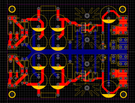
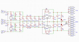
I've been working on a variant of Miro's PSU 1 with a few changes.
I have separate transformers for my 12v and 5v so I don't need both on 1 PSU.


I have opted for a central ground bus down the centre of the PCB rather than using a pour as would probably be my normal custom. Mainly to make sure the current paths from the bulk caps go where I want them.
Does anybody see any glaring issues or things I may have missed?
I've been working on a variant of Miro's PSU 1 with a few changes.
I have separate transformers for my 12v and 5v so I don't need both on 1 PSU.
- extra snubber cap across the transformers secondaries.
- larger heatsinks as I have a bunch of these lying around.
- 18mm diameter caps at the input and output as I have a bunch of these on hand.


I have opted for a central ground bus down the centre of the PCB rather than using a pour as would probably be my normal custom. Mainly to make sure the current paths from the bulk caps go where I want them.
Does anybody see any glaring issues or things I may have missed?
I only found this, maybe I already posted it here, I don't remember. Basically I'm only interested in PCM63 right now. With 100ohm I/V on PCM63, it is enough to have about 15x voltage gain. If I ever do a tube stage for PCM63, it will be something like this.Some measurements for PCM with higher values of Riv are already done and published but seems no-one care.
http://www.dddac.de/pcm63/DAC_I-V_Resistor.htm
Yes it would be a good choice. The amplification factor is slight less, but with preamp before the power amp will be more than needed.would D3A in triode mode do a good job?
With Tube preamp after doc D3a output buffer is not a must because the output resistance will be Ri parallel with Rload, and that is according to data sheets around 1.5K (if 5.5K Rload applied). At linear region of Ug=-1.375V (Rk=62.5ohm), Ia=22mA, Va=160V.
The Ck bypassing cathode capacitor will be higher value probably more than 2200uF. It has to be bypassed because of needed Gain and to avoid local feedback. But You can Use AA battery in cathode of 1000mA/h than You will get around 1.2V negative grid bias, no need for Ck capacitor and higher gain.
I used in PCM63 DAC for decades Sowter 8347 (1:18.7) I/V transformer and 2k load on secondary (and Siemens Cca tube buffer).Basically I'm only interested in PCM63 right now.
The reflected impedance only few Ohms on DAC chip output.
It sounded more better, than any resistive load.
p.s.
Read conversations here:
https://www.diyaudio.com/community/threads/pcm56-dac-power-supply-question.375213/page-2
Last edited:
Yes but that is only down to 100ohms. And You can see the diff. But some members use 200ohm or more inspired of these facts... Again, sound is good...I only found this, maybe I already posted it here, I don't remember. Basically I'm only interested in PCM63 right now. With 100ohm I/V on PCM63, it is enough to have about 15x voltage gain. If I ever do a tube stage for PCM63, it will be something like this.
http://www.dddac.de/pcm63/DAC_I-V_Resistor.htm
.
Some guy before years posted a measurements with even current p-p measured, I think I saw this photo earlier in the topic. But this measurements taken with Riv and transformer. Anyway could be of use.
The difficulty is to match two tubes as dissipation production is large enough in a stereo context. Also, big Mu, easy oscillations = not for beginners.would D3A in triode mode do a good job?
you mean one is needing a good virtual "back-ground" to listen to tubes 😉 ?I thought you don't care about any measurements with tubes, but just listen ?
Especially with passive IV at current pin out.
😊
Patrick
D3a TFK or Siemens when NOS are excellent. From my experience they are very close to identical. It is a mju of 70cca like 6SL7, ECC81 or other tubes... But maybe little larger capacitances. Standard measures for potential HF oscillation are ok.
.
For these conditions of small input signal range of say 0.05 Vp-p and say 70X output 3.5Vp-p distortion of very linear tube, with good choice of most linear region distortion can be very very small.
It is not driver tube giving a voltage all over the HV region and huge -Ug values and currents.
Or power tube reaching the max swing to "milk" the last mW...
- Home
- Source & Line
- Digital Line Level
- DAC AD1862: Almost THT, I2S input, NOS, R-2R