The issue of the baffle shape and thickness for my OB project still isn't resolved. I was concerned about the 5208 response circa 1 khz, where directivity changes for some as then unknown reason. This is how it looked in the system simulation post equalization:

so I ran a bunch of sims and compared results

The most telling trace is the (green) rear wave. Except for the spike around 1600 Hz, which is likely a simulation artifact. I'd say that the 12 mm result is the best. The upper right is for a front mounted driver recessed flush with a 45 degree backside bevel. Its almost as good as the 12 mm thick result and doesn't have the discontinuity at 1600 Hz.
The recess 12, bevel 24 on a 36mm baffle produced nice polars, the best so far:


so I ran a bunch of sims and compared results
The most telling trace is the (green) rear wave. Except for the spike around 1600 Hz, which is likely a simulation artifact. I'd say that the 12 mm result is the best. The upper right is for a front mounted driver recessed flush with a 45 degree backside bevel. Its almost as good as the 12 mm thick result and doesn't have the discontinuity at 1600 Hz.
The recess 12, bevel 24 on a 36mm baffle produced nice polars, the best so far:
@ pelanj, very cool. Glad to hear your are playing with open backs too. Will keep close watch for your posts on them.
For sure. Nothing wrong with perfect polars...wish I could get them easily....just 'cause.
My experiments with and without secondaries were mainly about "whether or not differences are so great as to affect our enjoyment of the music".
I could see polar measurements improved with secondaries, but i could not tell it made a significant difference in the listening experience....either indoors or out.
We all choose what mountain(s) to climb. I try to choose the one(s) the give me vision on how to make future decisions.
I particularly value info on what factors provide the greatest marginal gains,...... and how much time, effort and expense to put into their optimization.
I see the sim above is for a coaxial 12" and CD/waveguide on a conical horn. Cool. Thx.
I tried putting a horn" around the 15cxn88, with the idea I'd try to copy what Danley does with their SM-80, that uses a 12" B&C coaxial.
It worked OK, but I never could get polars as nice as when the horn was removed. And then it sounded good, but not so good in comparison to other projects.
So I'm kinda looking forward to trying the driver in the OB design that Perry has given the community. See what the driver might be capable of...
I don't think though, I'd try again to use a large coax, say one greater than 10", in any kind of larger horn. A flat baffle, yes. But a horn, no.
There is nothing wrong with "perfect" polars. I don't think its a craze; it's a mountain that just became climbable so of course we are climbing it.
The question is whether or not perfect polars are necessary. Its not so much whether our ears can discriminate between the sounds of perfect/imperfect polars but whether or not differences are so great as to affect our enjoyment of the music. I do know that one can get the sound of a simple conical equalized quite enjoyably within a listening window. the more controlled the directivity, the wider that listening window can be.
For sure. Nothing wrong with perfect polars...wish I could get them easily....just 'cause.
My experiments with and without secondaries were mainly about "whether or not differences are so great as to affect our enjoyment of the music".
I could see polar measurements improved with secondaries, but i could not tell it made a significant difference in the listening experience....either indoors or out.
We all choose what mountain(s) to climb. I try to choose the one(s) the give me vision on how to make future decisions.
I particularly value info on what factors provide the greatest marginal gains,...... and how much time, effort and expense to put into their optimization.
I see the sim above is for a coaxial 12" and CD/waveguide on a conical horn. Cool. Thx.
I tried putting a horn" around the 15cxn88, with the idea I'd try to copy what Danley does with their SM-80, that uses a 12" B&C coaxial.
It worked OK, but I never could get polars as nice as when the horn was removed. And then it sounded good, but not so good in comparison to other projects.
So I'm kinda looking forward to trying the driver in the OB design that Perry has given the community. See what the driver might be capable of...
I don't think though, I'd try again to use a large coax, say one greater than 10", in any kind of larger horn. A flat baffle, yes. But a horn, no.
In light of last night's discussion, I just had to try mounting the driver flush on the rear of the baffle and then bevelling towards the front, which hopefully would provide a termination of sorts for the conical horn and further improve the results.
It only took a few minutes to rearrange the driver and bevel.

The SPL curve looks pretty much like the front mount/bevel rear SPL, except the rear wave trace slopes slightly downward towards HF:

The polar maps were a surprise in that the side nulls from 400 Hz up were not as deep


the decreased depth didn't prevent me from obtaining an pleasing smooth system simulation result but it does seem to have resulted in deeper boundary nulls (overlay trace below)

Rearmounting cleans up the front of the baffle and allows the driver to be isolated from it:

I like that but I would prefer not to lose the deep dipole side nulls so I have more work to do...
It only took a few minutes to rearrange the driver and bevel.
The SPL curve looks pretty much like the front mount/bevel rear SPL, except the rear wave trace slopes slightly downward towards HF:
The polar maps were a surprise in that the side nulls from 400 Hz up were not as deep
the decreased depth didn't prevent me from obtaining an pleasing smooth system simulation result but it does seem to have resulted in deeper boundary nulls (overlay trace below)
Rearmounting cleans up the front of the baffle and allows the driver to be isolated from it:
I like that but I would prefer not to lose the deep dipole side nulls so I have more work to do...
More precisely, it's for a 12" coax in which the woofer's cone acts as a conical horn and it's a gross approximation.I see the sim above is for a coaxial 12" and CD/waveguide on a conical horn.
The sim I just posted myself was for a 8" CD whose woofer cone acts as a conical horn, with a small secondary flare provided by the bevel through the baffle.
Aaah, gotcha.More precisely, it's for a 12" coax in which the woofer's cone acts as a conical horn and it's a gross approximation.
That's what i was trying to do with the 15cxn88...extend the woofers cone with secondary horn flares.The sim I just posted myself was for a 8" CD whose woofer cone acts as a conical horn, with a small secondary flare provided by the bevel through the baffle.
Fwiw, I've been told the secondaries on such a design, must have a wider angle than the woofer cone...hopefully widening in a smooth arc.
I wish I could replace the coax driver with a small ROSSE derived (ATH) synergy with open back mids. I'm still hoping that someone with more CAD and 3D printing skills than me will design one I can use.
What is the advantage of coax over independent drivers such as the B&C 4NDF34s in a synergy?
live edge dipole 150hz crossover looks like thisCool to see the analysis. So, with @perrymarshall's Live Edge I believe he's crossing over at 200 Hz with a... hmmm, not sure which slope,
https://www.diyaudio.com/community/...ion-updated-design.405104/page-2#post-7500040
The only advantage is that you can buy one off the shelf, as opposed to DIYing a synergy. I expect that a well-done synergy would have better polars but I'm with Mark100 on whether that would make the music more enjoyable - not sure that it would.What is the advantage of coax over independent drivers such as the B&C 4NDF34s in a synergy?
and...What is the advantage of coax over independent drivers such as the B&C 4NDF34s in a synergy?
Ok, I was wondering why Danley uses a 1x5" coaxial in their SM-60M. I guess it's just the manufacturing advantage like you pointed out.
I think there is are pattern control & SPL & low freq extension goal differences, in a synergy that uses 4NDF34's, and one that uses a only a 1x5" coaxial.
Small mids like the B&C's are a bridge between a powerful CD, and large cones pulling low-mid /upper bass duty. Higher SPL design.
A 1x5" coax is going to limited by the 5" section, and isn't really aiming to be more than an excellent small box design.
Personally, i use small-mids like the 4NDF34's not so much for SPL, but because I think using them sounds better than asking a CD to span too many octaves.
Seems to me that taking a CD too low, diminishes the presumed benefit of going as low as possible. (some form of modulation distortion perhaps??)
Anyway, like mentioned earlier..I'm focused on musical enjoyment..pretty much 100%....so my takes may well be entirely my own.
I have no doubt 4 4NDF34's in a synergy of similar size could replace the coax driver here. Together they have about 10% more volume displacement than the coax's woofer.
I'm still reviewing baffle thickness, front vs rear mount, bevel options for the coax.
The rear mount, front bevel version of post #163 gave me the smoothest response through the problematic 1 khz region that I've seen but compromised the directivity. I'm hypothesizing that the front bevel extended the directivity or reduced the diffraction so that less radiation found its way towards the back of the baffle to be canceled. My efforts to try different bevel angles thwarted by meshing difficulties. One of the frustrations with this method of ABEC is that it often gives up trying to produce a mesh, forcing you to try multiple MeshFrequency and EdgeLength specifications within the code to help it through the problematic detail. Eventually, one has to resort to CAD and/or external mesh software to produce the mesh (like ATH does).
Instead of that, I stepped back and took a close look at the work I had already done.
The 36 mm thick, flush front mount, no bevel, no HinB, has a nice extended composite response but some "jaggies" on the rear wave circa 1 khz that compromise the system response and introduce an off axis null near 800 Hz. Introducing a rear bevel cleaned up most of this but there were still issues near 1 Khz, albeit reduced.

The SPL graph of a flush rear mount, front bevel version is smoother but has the same issues near 1 khz as well as compromised directivity, as discussed earlier

The issue around 1 Khz seemed to have something to do with the vertical response. I wondered if re-introducing a HinB below the coax would help.

It helped a little bit. The green trace ramp from 750 Hz to 1100 Hz is perhaps 30% less tall. Except for that ramp, the green rear radiation trace is quite flat.
That is worth looking at in the Vituix system simulation.

The preference score using equation 1 is 9.46 and using equation 3 is 9.85. The linearity is 1 db.
The 100 hz to 1.2 khz is as good as one could want. Its misleading smooth above the 1200 Hz XO because the directivity there isn't based on the woofer's cone shape or the unknown tweeter throat shape. PerryMarshall's work shows us what to expect there.
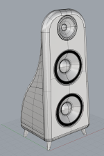
This is what it could look like rendered in Jatoba/Brazilian cherry:

I'm still reviewing baffle thickness, front vs rear mount, bevel options for the coax.
The rear mount, front bevel version of post #163 gave me the smoothest response through the problematic 1 khz region that I've seen but compromised the directivity. I'm hypothesizing that the front bevel extended the directivity or reduced the diffraction so that less radiation found its way towards the back of the baffle to be canceled. My efforts to try different bevel angles thwarted by meshing difficulties. One of the frustrations with this method of ABEC is that it often gives up trying to produce a mesh, forcing you to try multiple MeshFrequency and EdgeLength specifications within the code to help it through the problematic detail. Eventually, one has to resort to CAD and/or external mesh software to produce the mesh (like ATH does).
Instead of that, I stepped back and took a close look at the work I had already done.
The 36 mm thick, flush front mount, no bevel, no HinB, has a nice extended composite response but some "jaggies" on the rear wave circa 1 khz that compromise the system response and introduce an off axis null near 800 Hz. Introducing a rear bevel cleaned up most of this but there were still issues near 1 Khz, albeit reduced.
The SPL graph of a flush rear mount, front bevel version is smoother but has the same issues near 1 khz as well as compromised directivity, as discussed earlier
The issue around 1 Khz seemed to have something to do with the vertical response. I wondered if re-introducing a HinB below the coax would help.
It helped a little bit. The green trace ramp from 750 Hz to 1100 Hz is perhaps 30% less tall. Except for that ramp, the green rear radiation trace is quite flat.
That is worth looking at in the Vituix system simulation.
The preference score using equation 1 is 9.46 and using equation 3 is 9.85. The linearity is 1 db.
The 100 hz to 1.2 khz is as good as one could want. Its misleading smooth above the 1200 Hz XO because the directivity there isn't based on the woofer's cone shape or the unknown tweeter throat shape. PerryMarshall's work shows us what to expect there.
This is what it could look like rendered in Jatoba/Brazilian cherry:
Last edited:
I can do that, not a video, but a document; perhaps a slide show...
might take a little while as I'm absorbed in another project at the moment
in the interim you might go through the example projects
yes, this software takes some getting used too.
I start with a sketch/CAD drawing of what I want to model. With CAD, you can simply import meshed cad files into ABEC, which has its own set of problems discussed in a thread by @fluid. I trade those problems for the one of translating a cad drawing into a parameterized list of points in 3D space. It's really easy to create a box this way; gets progressively more complex as you add thickness to each surface, and/or have curves or bevels. ,,,,
With points defined you can use "baffle" block to define your baffle and place holes and driver diaphragms on it.
Elements blocks create non-baffle surfaces. WallImpedance block allows damping on walls, which is necessary to avoid internal standing waves....
All this is documented in the help file but there is very little tutorial there. examples are relied on instead.
that, not a video, but a document; perhaps a slide show...
might take a little while as I'm absorbed in another project at the moment
roblems for the one of translating a cad drawing into a parameterized list of points in 3D space. It's really easy to create a box this way; gets progressively more complex as you add thickness to each surface, and/or have curves or bevels. ,,,,
With points defined you can use "baffle" block to define your baffle and place holes and driver diaphragms on it.
Elements blocks create non-baffle surfaces. WallImpedance block allows damping on walls, which is necessary to avoid inte
Excellent! Thank you for these hints, much appreciated.
My model is indeed curved.
I already stumble with the meshing and import. The application seriously lacks feedback in the import process.
I'll do what you suggest
") Thanks a bunch.
Thanks a bunch.For my sims here, I did a simple piece wise linear approximation to the curve - just 4 points along the curved portion.
anything more than that you might be better off with importing mesh from CAD - if you have those skills.
best of both worlds might be to use mesh import selectively
if you have meshing problems, switch between Delauney and Bifu. sometimes one works better than the other.
I believe this can be done in an Elements block if needed
Control_Solver
f1=20; f2=3000; NumFrequencies=50;
Abscissa=log;
Sym=x;
Dim=3D
MeshFrequency=3000Hz
Meshing=Delaunay
//Meshing=Bifu
specify EdgeLength in problematic modules
don't place diaphragm edge too close to baffle edge
Nope. I'm letting ABEC do the meshing. I know gmesh works much better but I don't need the resolution because I'm only looking at directivity below 1200 Hz. I'm not trying to predict the tweeter's directivity. This is partly because I'm somewhat handicapped by having SketchUp burned into my muscle memory and never having been good at scripting (always had support for that in my day job). Sketchup does not mesh very well...
Your model is much nicer than mine, but that niceness will cost you in simulation time. I would build with roundovers but not simulate them (unless I got mesh import working well) arguing that the roundovers would only make it better. They are only big enough to be significant above a khz or so but likely only to affect results by tenths of a db because of midwoofer cone/waveguide keeping HF off the baffle edges.
I've got a AMD Ryzen 7 7700 8-Core Processor, 3801 Mhz, 8 Core(s), 16 Logical Processor(s) fanless case. I wish I had 16 cores but I work the models to keep the mesh resolution down where its not needed and so most sims, limited to 3k elements, run in a couple of minutes.
Your model is much nicer than mine, but that niceness will cost you in simulation time. I would build with roundovers but not simulate them (unless I got mesh import working well
) arguing that the roundovers would only make it better. They are only big enough to be significant above a khz or so but likely only to affect results by tenths of a db because of midwoofer cone/waveguide keeping HF off the baffle edges.I've got a AMD Ryzen 7 7700 8-Core Processor, 3801 Mhz, 8 Core(s), 16 Logical Processor(s) fanless case. I wish I had 16 cores but I work the models to keep the mesh resolution down where its not needed and so most sims, limited to 3k elements, run in a couple of minutes.
works much better but I don't need the resolution because I'm only looking at directivity below 1200 Hz. I'm not trying to predict the tweeter's directivity. This is partly because I'm somewhat handicapped by having SketchUp burned into my muscle memory and never having been good at scripting (always had support for that in my day job). Sketchup does not mesh very well...
I would have hoped to find a meshing tool for Rhino but they all seem to cater to wind simulations unfortunately.
I have been using Rhino since it's inception so I'm old in that game. I'm just not used to mesh for CFD.
Ah so you are saying that I wont see any noticeable results from this except baffle width and depth?
Thanks, so I can expect slightly slower simulation here at 25180 vs your 34631 CPU Mark score, good to know.
- Home
- Loudspeakers
- Multi-Way
- Dipole and Uframe models and discussion re' Live Edge Dipoles