Thank you.The bias resistor on Q2 sets the current to a value lower than Idss of the fet. It is optional. The bias resistor for Q1 is optional and only trims the DC setting. If I revise the board in the future I will probably drop the Q1 resistor and also replace the Q2 with the much less expensive J113 or similar.
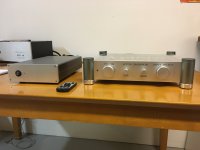
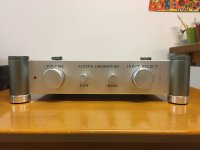
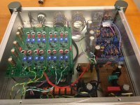
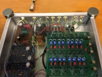
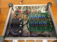
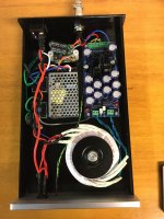
Here is my completed 6-24 active crossover in an integrated line stage. BA2018 line stage with Salas I-select input with Academy Audio VCU Muse volume control. The power supply is remote with a VRDN set to +18 -18vdc and a Meanwell hospital grade 24v SMPS with an SMPS filter in the power supply housing and another under the 6-24 PCB. Both power supplies have voltage adjustments, which I set under load. There is a +15 -15vdc regulator for the I-selec, VCU and Mute relay. The 6-24 has 24 postion 50K pots for low and high level, it uses 2SK170BL JFETs for the buffers. I used 6 matched pairs where the matching is left and right channels. I raised the 6-24 PCB and made a clear plexiglass cover with holes for the 6-24 adjusting pots.
Attachments

Wow. I wish I van go back to not knowing how complicated this project is.More pics.
Why do you have both an smps and smps filter and a linear power supply in the same box?
To reduce noise, the BA2018 line stage seems sensitive to noise and hum.Why do you have both an smps and smps filter and a linear power supply in the same box?
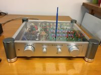
@elwood625 did you do all the casework yourself? It's impressive and very beautiful.
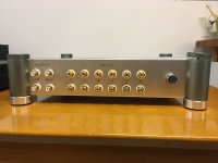
I drilled all the holes, Front Panel Express did the lettering. Wish I had a machine like that.did you do all the casework yourself? It's impressive and very beautiful.
with this sophisticated build, i can only suggest to replace smps with linear supply like Salas BiBHere is my completed 6-24 active crossover in an integrated line stage. BA2018 line stage with Salas I-select input with Academy Audio VCU Muse volume control. The power supply is remote with a VRDN set to +18 -18vdc and a Meanwell hospital grade 24v SMPS with an SMPS filter in the power supply housing and another under the 6-24 PCB. Both power supplies have voltage adjustments, which I set under load. There is a +15 -15vdc regulator for the I-selec, VCU and Mute relay. The 6-24 has 24 postion 50K pots for low and high level, it uses 2SK170BL JFETs for the buffers. I used 6 matched pairs where the matching is left and right channels. I raised the 6-24 PCB and made a clear plexiglass cover with holes for the 6-24 adjusting pots.
Here with a better drawing again my questions:
1. can I add for overall volume control an additional frontend to the existing front end (marked with yellow marker)?
2. can I remove the coupling caps and the connections to VREF in the existing front-ends (red circles)?
Thanks for your feedback.

1. can I add for overall volume control an additional frontend to the existing front end (marked with yellow marker)?
2. can I remove the coupling caps and the connections to VREF in the existing front-ends (red circles)?
Thanks for your feedback.
Last edited:
I think this is irrelevant, as these to pots are trimmers to be set once.If you will have small voltage on the buffer output, it may cause scratchy sound in the volume pots. I would suggest to use one cap on the buffer output. Just like B1.
- Home
- Amplifiers
- Pass Labs
- DIY biamp 6-24 crossover