I still don’t know how to set it, but I can guess:
Let’s say I find out that it takes a 50ohm resistor to set a J113 with 30mA Idss to had similar Idss as a LSK170 that measured 15mA when I test it in my 9volt test rig with a 100ohm resistor on Source and Gate.
Then I put the 50ohm resistor as bias for J113 at Q2. lSK170 at Q1 gets 0 ohm (a wire) as its bias resistor, because NP told me so. Is this an okay example?
It might even work with Ohm’s Law! This feels so wrong…
V = IR
VJ113 = 30mA x 50ohm = 1.5V
VLSK170= 15mA x 100ohm =1.5V
And in this example, can I do that with a 67 ohm resistor for the J113? It came with a 100ohm resistor in the kit. I measured the J113 to have a 30mA Idss in my 9V, 100ohm resistor test rig.You wrote:
"My sixteen LSK170 [mA]: 27.4, 26.5, 25.8, 24.8, 24.6,...."
If you want to use these FETs as "upper" device, set "lower" J113 with its bias resistor -for example" to 20mA.
I'm afraid, that your IDSS measurings are false.
2SK170 datasheet:
"IDSS classification GR: 2.6~6.5 mA, BL: 6.0~12 mA, V: 10~20 mA"
https://www.google.hu/url?sa=t&rct=j&q=&esrc=s&source=web&cd=&ved=2ahUKEwjxlOXuw875AhVaP-wKHakTAhYQFnoECBIQAQ&url=https://www.mouser.com/datasheet/2/408/6909-57550.pdf&usg=AOvVaw3XyheFQXjPJXUf05c10VDP
I measured several (few hundred) K170 FETs, most of them GR, some BL, and only few of them over 12mA.
Try once more:

It -probably- results few mA (IDSS).
Try to set J113 CCS with this method lower current than "upper" K170 IDSS:


J113 datasheet

p.s.
Be sure, that pinout is OK:

2SK170 datasheet:
"IDSS classification GR: 2.6~6.5 mA, BL: 6.0~12 mA, V: 10~20 mA"
https://www.google.hu/url?sa=t&rct=j&q=&esrc=s&source=web&cd=&ved=2ahUKEwjxlOXuw875AhVaP-wKHakTAhYQFnoECBIQAQ&url=https://www.mouser.com/datasheet/2/408/6909-57550.pdf&usg=AOvVaw3XyheFQXjPJXUf05c10VDP
I measured several (few hundred) K170 FETs, most of them GR, some BL, and only few of them over 12mA.
Try once more:
It -probably- results few mA (IDSS).
Try to set J113 CCS with this method lower current than "upper" K170 IDSS:
J113 datasheet
p.s.
Be sure, that pinout is OK:
Attachments
Last edited:
PM sentSo I will just solder a wire in place of the bias resistor closest to 1K resistor in the input buffer, and put a LSK170 in place of the J113 at W1 at the input buffer. Which Idss should the LSK170 at Q1 in the input buffer have? Pick any value, I have 4-27mA.
This I don’t understand:
«and leave Q2 as a J113, but set it's bias resistor so that Q2 runs approximately at the Idss of Q1 or a bit less.» - NP
Should I take the 30-31.5mA J113 and LSK170JFETs and use my JFET test rig?:
+9V battery to Drain
-9V battery to 100ohm resistor
read Idss on both wires coming out of the resistor.
And then change the 100ohm resistor in the test rig to 150ohm, 200ohm, etc, until it matches the Idss of what I measured the LSK170 to be with a 9 volt and a 100ohm resistor yesterday? And then use this resistor, maybe 200ohm, in the 6-24 crossover as the BIAS resistor for the J113 in Q2?
I agree. These IDSS values can not be valid. For LSK’s they should be between 5-8mA.Back to LSK170 upgrade of Q1:
I measured my J113 and LSK170 JFETS included in the kit. With a new +9 volt battery connected to Drain, and "Gate + Source" connected to a 100ohm resistor. These are my results when I measured across the resistor:
From Kit: J113 measured very nice between 30-31.5mA with 100 ohm included BIAS resistor. "NP, get a hobby."
My sixteen LSK170 [mA]: 27.4, 26.5, 25.8, 24.8, 24.6, 18.0, 17.7, 15.85, 9.72 9.26, 9.22, 9.20, 8.45, 7.90, 7.74, 7.71, 7.57, 7.18, 6.8, 6.42, 6.21, 5.81, 5.78, 5.69.
Now add Ohm's law and voilà!
Not sure what to do now. Do I place all the J113 and start the circuit, and measure the mA over a BIAS resistor (which of them?), then calculate R=V/I, since I now know both mA and Voltage (do I)?
Pm sent.So I will just solder a wire in place of the bias resistor closest to 1K resistor in the input buffer, and put a LSK170 in place of the J113 at W1 at the input buffer. Which Idss should the LSK170 at Q1 in the input buffer have? Pick any value, I have 4-27mA.
This I don’t understand:
«and leave Q2 as a J113, but set it's bias resistor so that Q2 runs approximately at the Idss of Q1 or a bit less.» - NP
Should I take the 30-31.5mA J113 and LSK170JFETs and use my JFET test rig?:
+9V battery to Drain
-9V battery to 100ohm resistor
read Idss on both wires coming out of the resistor.
And then change the 100ohm resistor in the test rig to 150ohm, 200ohm, etc, until it matches the Idss of what I measured the LSK170 to be with a 9 volt and a 100ohm resistor yesterday? And then use this resistor, maybe 200ohm, in the 6-24 crossover as the BIAS resistor for the J113 in Q2?
Exact IDSS of the LSK’s is less important, as long as you keep bias at or a tad bit lower by adjusting the current through Q2.
this either involves experimenting in circuit, or making a copy of the biasing circuit on a breadoard, or soldering in socket pins to swap resistors until you get a match.
For example, if you choose LSK’s with IDSS of 9mA, set bias to 8,5mA or so through Q2. This involves first pairing LSK’s, then jumpering their bias resistors. Then you need to select a bias resistor for Q2 that keeps the current at or around 8,5mA.
Read this (first page):
https://www.diyaudio.com/community/threads/jfets-j113-2sk170-2n5457-and-others.340796/
https://www.diyaudio.com/community/threads/jfets-j113-2sk170-2n5457-and-others.340796/
Thanks!
It will take me som time to process what you answered.
What was it on the first page you in the link that you wanted to show?
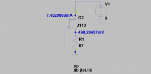
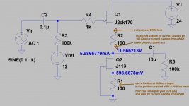
Thank you for the help, but Andynor talked me out of it. I have three PCBs, so maybe I will experiment with Toshiba parts on the last one - after I am done with the first two using the included Fairchilds. The learning «slope» is just too steep. Dad joke.Sample:
In this case (measured CCS current) you must use more than 7mA IDSS K170.
View attachment 1082061
But, the trouble continued…
1. R-C filters
How come I see so many variations of the same thing? Sometimes C is equal for both Lo and Hi pass, and sometimes Lo pass is double, but it just works.
I guess one limiting factor is availability of nanofarad capacitors, and this requires some creativity. At least refer me to good a book to teach me about how to program the calculator.
2. Slopes
How can anyone be certain that their slope is Linkwitz-Riley 24dB slope, a Butterworth 12dB slope, or a Benedict Cumberbatch 48dB slope? I made the last one up.
3. Pots in Slots
What is up with that? Do you really need to take out the pots to adjust them? Or is it just for poor people without a tone generator and oscilloscope?
Last edited:
post1155:
1:
you have to choose an available value of capacitors (in nF) and then you adjust the R (resistor) to get the desired crossoverfrequency in a R-C-filter.
2:
You choose how steep your slope shall be - 6dB attenuation per octave or 12dB attenuation per octave, 18dB, 24dB,...
3: you can also count your amount of turns for the trimpots. Adjust the trimpots for the left and right channel
(in the same filter) to the same amount of turns.
But how do you know the resistance of your trimpot? And don't forget to add the fixed resistor value before the pot. How will you adjust the trimpot to your resistance from the simulation in Mike Rothachers simulator?
Only some thoughts.
Cheers
Dirk
3. It seems the pots are only using two out of three legs, which makes measuring resistance less hocus pocus. Last sentences in the article:
"Here is the board layout with those custom part locations. Note that resistor values SLR1, SLR2, SHR1 and SHR2 are those resistors in series with the P1 and P2 potentiometers on each filter. In the standard version they are 10 Kohm in series with the 50 Kohm potentiometers." NP
"Here is the board layout with those custom part locations. Note that resistor values SLR1, SLR2, SHR1 and SHR2 are those resistors in series with the P1 and P2 potentiometers on each filter. In the standard version they are 10 Kohm in series with the 50 Kohm potentiometers." NP
- Home
- Amplifiers
- Pass Labs
- DIY biamp 6-24 crossover