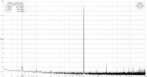
Can attest to the single ended loop noise. (this is me playing around because I'm mad and searching for the quietest power supply, not a finished config)
The best result I got: Hypex SMPS, only one channel from a Topping E30II dac connected to one channel of a stereo wolverine.

(Please ignore harmonic distortion, its the load bank and the DAC)
Them mono block builders might be on to something...
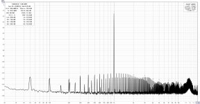
The moment both channel inputs are connected it all turned rotten. (I was later able to tidy it up a bit with different wiring approaches)

The best result I got: Hypex SMPS, only one channel from a Topping E30II dac connected to one channel of a stereo wolverine.

(Please ignore harmonic distortion, its the load bank and the DAC)
Them mono block builders might be on to something...
The moment both channel inputs are connected it all turned rotten. (I was later able to tidy it up a bit with different wiring approaches)

@fireanimal, very nice work. Is it too much to ask for a schematic so we can see and learn how you pulled it off to get such good results ?
Thanks, I can but I will post in the new thread when I start it.
Finally got around to working on the Wolverine again after being very busy working on my bachelor's degree (nearly there!).
Installed the output transistors today (after testing w/out) and mounted one of the channels to the heatsink.
I think i am quite happy with how it turned out, though any feedback is appreciated since i'm in no way experienced in building stuff like this. Now for anxiety testing everything for shorts and powering it with the Cobra for the first time 🙂
Hi Mainframe,Can attest to the single ended loop noise. (this is me playing around because I'm mad and searching for the quietest power supply, not a finished config)
The best result I got: Hypex SMPS, only one channel from a Topping E30II dac connected to one channel of a stereo wolverine.
View attachment 1321065
(Please ignore harmonic distortion, its the load bank and the DAC)
Them mono block builders might be on to something...
The moment both channel inputs are connected it all turned rotten. (I was later able to tidy it up a bit with different wiring approaches)
View attachment 1321066
I have done a fair bit of measurement of this sort and with most amplifiers once you close the measurement loop around the amplifier this "fishbone" behaviour happens. In practice a speaker is connected to the output so there is no loop return via the amplifier to the measurement system when you are listening to music.
For measurements though.....
USB isolators help, USB powered dacs help (I.e. d10s etc) isolation transformers can help but ultimately any common mode noise, rubbish, leakage, power supply artifacts present on the signal side will show up and be amplified on any single ended input amplifier.
Balanced inputs really do help here since common mode rejection can be quite high if done correctly.
I am sure you know all this but I thought I should mention it for the less experienced.
Also, if you are measuring 5W and looking at the noise floor it is going to visually look alot worse than measuring 50W or 200W for example since you will attenuate the signal as well as the noise going to the ADC used for measurement and distance between the signal and the noise floor is further on the FFT.
Hope this is useful.
One last thing, switched mode power supplies often have less leakage current near the mains supply frequency since the transformer in an smps is typically physically smaller and has less capacitive coupling to ground. And clearly operate at a much higher frequency. In a linear power supply if you use a traditional transformer with a interwinding screen this can help to reduce leakage current also.
I hope this is useful
- Dan
Were you in the group buy? emailed as a dropbox link.
Yup, should be rule #1 with measurements - the only mains should be at the DUT, if at all.Hi Mainframe,
I have done a fair bit of measurement of this sort and with most amplifiers once you close the measurement loop around the amplifier this "fishbone" behaviour happens. In practice a speaker is connected to the output so there is no loop return via the amplifier to the measurement system when you are listening to music.
For measurements though.....
USB isolators help, USB powered dacs help (I.e. d10s etc) isolation transformers can help but ultimately any common mode noise, rubbish, leakage, power supply artifacts present on the signal side will show up and be amplified on any single ended input amplifier.
Balanced inputs really do help here since common mode rejection can be quite high if done correctly.
I am sure you know all this but I thought I should mention it for the less experienced.
Also, if you are measuring 5W and looking at the noise floor it is going to visually look alot worse than measuring 50W or 200W for example since you will attenuate the signal as well as the noise going to the ADC used for measurement and distance between the signal and the noise floor is further on the FFT.
Hope this is useful.
One last thing, switched mode power supplies often have less leakage current near the mains supply frequency since the transformer in an smps is typically physically smaller and has less capacitive coupling to ground. And clearly operate at a much higher frequency. In a linear power supply if you use a traditional transformer with a interwinding screen this can help to reduce leakage current also.
I hope this is useful
- Dan
Have a resistor question that might not have an answer, but welcome input.
I have access to NOS (new old stock) carbon film and carbon composite resistors. I have read all types of conflicting information on using them.
Such as they need to be replaced after some time due to degradation. As well as they are noisy compared to good metal film resistors (ie Vishay).
I believe the carbon resistors that I have access to are all only 5% tolerance, so I had to hunt for ones that are within a couple of Ohms of say 100 Ohm resister in a schematic.
Any thoughts ????
My advice, spend the extra money on quality resistors.
Carbon resistors went out in the '80's, use metal film...
Saving cents and dimes while degrading your amp. Not worth it.
Nice Non inductive resistors, close specs to the mra-05 ones I am trying to let go https://www.vishay.com/docs/31801/mra.pdf
https://www.diyaudio.com/community/threads/some-components.314633/
https://www.diyaudio.com/community/threads/some-components.314633/
For input tr pairs , can I use higher voltage type like bc 550?
And why is bc 549 is chosen as default?
And why is bc 549 is chosen as default?
BC550/560 are totally fine. BC550/560 are obsolete but BC549/559 are still available.
Jeremy
Jeremy
- Home
- Amplifiers
- Solid State
- DIY Class A/B Amp The "Wolverine" build thread
