2SC3503E and 2SA1381EIs this combination ok for 4 ohm load and +- 57V power supply? Am using 8 output transistors version of PCB.
Pre Driver: TTC004BQ - TTA004BQ
Driver: 2SC4793 - 2SA1837
Outputs: NJW3281G - NJW1302G
Any better combination recomended?
Or
KSC3503E and KSA1381E
Are the best choice for Pre-Drivers
The rest of your components are a good choice.
Are the KSC3503DS and KSA1381ESTU avalable from mouser ok?2SC3503E and 2SA1381E
Or
KSC3503E and KSA1381E
Are the best choice for Pre-Drivers
The rest of your components are a good choice.
I was planning to use TTC004BQ - TTA004BQ on Wolverine input board. Better to replace those with KSC3503DS and KSA1381ESTU also?
Yes.Are the KSC3503DS and KSA1381ESTU avalable from mouser ok?
I was planning to use TTC004BQ - TTA004BQ on Wolverine input board. Better to replace those with KSC3503DS and KSA1381ESTU also?
Try and get a 2SA1381E or KSC3503E.
I'll send you a pm.

Since they don't make _SC3503 'E' anymore, and you're not lucky enough to find the 'E' version then is there possibly other options for the higher voltages (60-70v)?
I've also had trouble getting matching MJE15032/33 'G' drivers. Closest hFE matches I have is 88 NPN & 116 PNP out of 60 pieces. Most NPN measure in the ~85 range and PNP in the ~120 range. (all from Mouser, measured with a DCA75 Pro)
Are there other, better options that aren't listed? Are these poor matches useable? I'm using MJL4203AG / MJL4281AG outputs at +/-70v. What happens if these poor matches are used? Is there some way to compensate for poor matches?
TIA
I've got mica caps on the way. I am replacing the standoffs with nylon and have plastic washers on the way. I will remove D105b and D106b and replace with wire jumpers. I've decided to scrap the MJL21193/4 combo and will go with the MJL4281/MJL4302 combo. You guys are the bomb, finding these kinds of small but important changes from a photo, THANK YOU! I guess the outputs aren't so small but thanks again. When I read the data sheet ont he MJL21193/4 combo and saw 3Mhz, I scratched my head.Looking good Rick.
Please refer to post #95...
Also.
1. Are you not planning on running mica caps.
2. Watch your creepage of your bolt heads. Please use a plastic washer or a socket head cap screw
This stuff is starting to make a little sense.
Yes mine has arrived too, I think I have read that thread 3 times now. Would be great for info on correct usage, and what components are necessary to be populated? Thanks!greglo3a:
Your transistor matcher board has arrived -- I can't wait to start populating it! Any chance you've uncovered a BOM for the board? It seems the BOM is no longer available on the original thread (the dropbox link is broken). The schematic provides guidance on most but not all of the components.
Many thanks,
Scott
I have the same issue here, only worse, ~85 and ~205. I only bought 4 pcs of each though.I've also had trouble getting matching MJE15032/33 'G' drivers. Closest hFE matches I have is 88 NPN & 116 PNP out of 60 pieces. Most NPN measure in the ~85 range and PNP in the ~120 range. (all from Mouser, measured with a DCA75
Should there be the need to match driver transistors?I've also had trouble getting matching MJE15032/33 'G' drivers. Closest hFE matches I have is 88 NPN & 116 PNP out of 60 pieces. Most NPN measure in the ~85 range and PNP in the ~120 range. (all from Mouser, measured with a DCA75 Pro)
Gaetano.
One protype board that was tested had none of the transistors matched. The THD was extremely low.Should there be the need to match driver transistors?
Gaetano.
Hope that helps.
Found this in the other thread, hope it helps someone here.Yes, disparity in the driver is concerning. I ran your scenario with the driver NPN hfe=130 and PNP hfe=210 in sim. I saw 20kHz .000103% THD with the drivers matched and 20kHz .000109% THD for your situation. Needless to say but the distortion was hardly affected. The current mirror and the TMC feedback really throw the distortion into the mud. The current mirror is the most important to match along with it's emitter resistors.
The 2sc5171/2sa1930 trade SOA for speed, because of this I don't recommend them as drivers for 4ohm use greater than 50V rails.
Jeremy
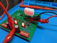
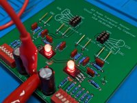
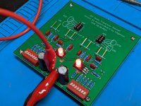
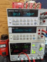
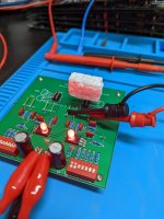
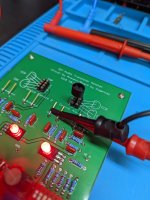
Ok so managed to get this built with some spare parts and salvaged DIP switches lol.
BOM for those interested;
R1,R2,R21,R22 - 10K .1% or better Matched
R3,R4,R19,R20 - 100R .1% or better Matched
R5,R18 - 1K
R6,R17 - 62R
R7,R16 - 82R
R8,R15 - 120R
R9,R14 - 240R
R10,R13 - 620R
R11,R12 - 1K
D1,D2 - 3mm LED
C1,C2 - 100uF
C3-C10 - .01uF
Any errors please let me know.
I also assume DIP 1 and 2 on is roughly 3 mA current? Please confirm.
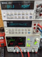
EDIT - My Matches measured with 4 Wire
100R - 99.923 | 99.918 , 99.913 | 99.910
10K - 9.99599 | 9.99583 , 9.99257 | 9.99181
BOM for those interested;
R1,R2,R21,R22 - 10K .1% or better Matched
R3,R4,R19,R20 - 100R .1% or better Matched
R5,R18 - 1K
R6,R17 - 62R
R7,R16 - 82R
R8,R15 - 120R
R9,R14 - 240R
R10,R13 - 620R
R11,R12 - 1K
D1,D2 - 3mm LED
C1,C2 - 100uF
C3-C10 - .01uF
Any errors please let me know.
I also assume DIP 1 and 2 on is roughly 3 mA current? Please confirm.
EDIT - My Matches measured with 4 Wire
100R - 99.923 | 99.918 , 99.913 | 99.910
10K - 9.99599 | 9.99583 , 9.99257 | 9.99181
Attachments
Last edited:
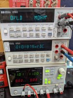
Yes it does, lucky for me all my HFE matches with my PEAK have all matched around +-0.5mV or better so far! And as stated in the matcher thread Close contact is key as well as blocking air currents, I placed a box over the whole thing while I measured.Thanks for the BOM, I will pick-up my boards tomorrow. I had 10 made. Nice to see that it works extremely well.
I used these, had a bunch from another project - Digikey P4713-ND | ECQ-V1103JMOne last question, what's the lead spacing on the .01uF film caps?
- Home
- Amplifiers
- Solid State
- DIY Class A/B Amp The "Wolverine" build thread