Folks:
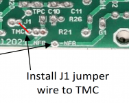
I've just begun soldering the IPS board and have what is likely a dumb question: does TPC need to be connected to TMC with a jumper? There are two lines at J1 -- one connects TMC to NFB and the other connects TMC to TPC. The Build Guide only mentions the TMC - NFB connection. Is the line between TMC and TPC a mistake?
Don't worry, I'll have plenty more dumb questions before this build has been completed.
Thank you,
Scott
Ok so managed to get this built with some spare parts and salvaged DIP switches lol.
BOM for those interested;
R1,R2,R21,R22 - 10K .1% or better Matched
R3,R4,R19,R20 - 100R .1% or better Matched
R5,R18 - 1K
R6,R17 - 62R
R7,R16 - 82R
R8,R15 - 120R
R9,R14 - 240R
R10,R13 - 620R
R11,R12 - 1K
D1,D2 - 3mm LED
C1,C2 - 100uF
C3-C10 - .01uF
Any errors please let me know.
I also assume DIP 1 and 2 on is roughly 3 mA current? Please confirm.
EDIT - My Matches measured with 4 Wire
100R - 99.923 | 99.918 , 99.913 | 99.910
10K - 9.99599 | 9.99583 , 9.99257 | 9.99181
How long did they take to settle, and was the meter in average function?
I left them around 5 minutes. My meter was set for 3hz AC filter and 6 digit slow reading. I did not average just let it settle, once it started bouncing back and forth a few mV I knew it was good.How long did they take to settle, and was the meter in average function?
Just an FYI too, the PEAK DCA75 Pro has roughly hit 90-95% on my matches, most are less then 1 mV some are around 0.1 mV and some that it measure the same HFE were around 3-5 mV, but for the most part its made my matching way easier.
J1 to TMC, see below from the build guideFolks:
I've just begun soldering the IPS board and have what is likely a dumb question: does TPC need to be connected to TMC with a jumper? There are two lines at J1 -- one connects TMC to NFB and the other connects TMC to TPC. The Build Guide only mentions the TMC - NFB connection. Is the line between TMC and TPC a mistake?
Don't worry, I'll have plenty more dumb questions before this build has been completed.
Thank you,
Scott
Attachments
I would say 1000% better then just random from the bag. See post #164Are transistors matched with Peak DCA75 Pro good enough for this amp?
TMC and TPC are abbreviations for different frequency compensation methods.Folks:
I've just begun soldering the IPS board and have what is likely a dumb question: does TPC need to be connected to TMC with a jumper? There are two lines at J1 -- one connects TMC to NFB and the other connects TMC to TPC. The Build Guide only mentions the TMC - NFB connection. Is the line between TMC and TPC a mistake?
Don't worry, I'll have plenty more dumb questions before this build has been completed.
Thank you,
Scott
Frequency compensation usually has two primary goals: To avoid the unintentional creation of positive feedback, which will cause the amplifier to oscillate, and to control overshoot and ringing in the amplifier's step response. It is also used extensively to improve the bandwidth of single pole systems.
The miller capacitors are C4 & C5
TMC = Traditional Miller Compensation.
TPC = Two Pole Compensation (not tested)
You cannot install both jumpers. Only one should be selected and installed.
Further information
Hope that helps.
Folks:
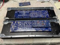
My Wolverine project has only just begun. I am building an integrated amplifier for my parents and the plan is to fill a 3U 400mm chassis to the brim. The chassis arrived earlier this week and includes the Wolverine variant on the UMS drill pattern. Kudos to the Wolverine team and HiFi2000 for all their incredible work!
Regards,
Scott
Attachments
I think PEAK DCA75 Pro is a great device.
I would say 1000% better then just random from the bag. See post #164
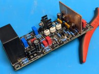
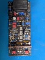
Looking good.Small milestone! 1 of 6 Input boards complete
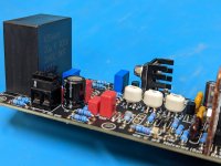
Are you able to apply some solder to the top of the pads to help secure the component and create a better connection. 🙂
It looks a lot better to. 😊
See a small snapshot from Daniel's board
Attachments
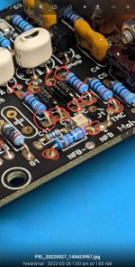
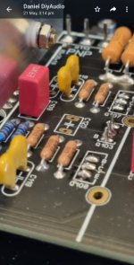
Thanks! I've never soldered both sides of a PTH PCB before? I see some joints did not get full flow through but the solder is in the PTH right below the pad, so mechanically it is good. Only issue I can see is if the board needs rework, it will be a real pain to remove the components if they are soldered both sides. It maybe more personal choice to solder both sides, but really at the end of it all I am just an amateurLooking good.
Are you able to apply some solder to the top of the pads to help secure the component and create a better connection. 🙂
It looks a lot better to. 😊
See a small snapshot from Daniel's board
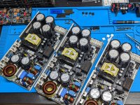
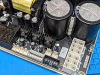
Power supplies just arrived, cant wait to test them out! Microaudio Cobra-S2
What's the output voltage of your SMPSs?
+-63What's the output voltage of your SMPSs?
Thanks! I've never soldered both sides of a PTH PCB before? I see some joints did not get full flow through but the solder is in the PTH right below the pad, so mechanically it is good. Only issue I can see is if the board needs rework, it will be a real pain to remove the components if they are soldered both sides. It maybe more personal choice to solder both sides, but really at the end of it all I am just an amateur
Applying some heat and a little solder on the top side will draw it up from the bottom and through the PTH giving you a more reliable connection. Reinspect the bottom connection for sufficient solder. There should be 100% coverage around the lead to the PTH.
Removing parts should not be anymore difficult other than maybe removing a little extra solder.
Jeremy
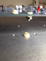
I have been trying to find a way to reliably isolate metal screws and spacers from pcb tracks on both the input and main pcb's. Ended up using those TO126 plastic mounting washers and slightly adjusting my spacer length. I have a collection of those washers so not sure where to buy. Perhaps this will help if you are stuck.
Attachments
- Home
- Amplifiers
- Solid State
- DIY Class A/B Amp The "Wolverine" build thread