This is a bom of the most currently revised transistor matcher, hence, it will require modification based on the older version that I sold. For example, the dip switch required is a 6 position NOT the 8 position listed in this BOM, also you won't need to purchase all the resistors listed because of the 8 position dip listed in this BOM. So just subtract 2 of the listed resistors that are specific to the dip switch. Remember you can exclude the caps parallel to the precision resisters. The schematic attached is correct for the matcher board I've been selling
Attachments

View attachment 1059805
If anyone in the US is having trouble sourcing or making the inductor, I’m willing to make extra epoxy dipped coils for $10 shipped per pair. Pm if interested, I probably have enough wire for a dozen coils.
Dumb question, what is the proper name of the type of meter that can measure low inductor coils like these?
Any suggestions of a decent economical meter to do such measuring?
LCR meter. If you follow the build guide on wire size and dimensions, you shouldn't need to measure them, they will be close enough. There are also calculators online for air core inductors, which calculate inductance by size/turns.Dumb question, what is the proper name of the type of meter that can measure low inductor coils like these?
Any suggestions of a decent economical meter to do such measuring?
Just measured my output transistors out of curiosity, all the NPN transistors are around 108hfe and my PNP are around 70hfe. I am using 2SA1943N and 2SC5200N. Is this OK or should I just order another batch of both and hope I can get them closer in hfe?
edit - just checked post 150 maybe this is ok ?
edit - just checked post 150 maybe this is ok ?
Build Guide recommends min 8mm and max 10mm.What is the minimum standoff height if mounting the board parallel to the heatsink? I was planning on 10mm, but it might be good to check. I am running 71V rails.
Personally, I think 10mm leaves too little lead length on the EF3-4 boards for safe soldering the Vbe TO126 transistors, especially if their leads are bent conservatively a little further from the transistor body.
This is a bom of the most currently revised transistor matcher, hence, it will require modification based on the older version that I sold. For example, the dip switch required is a 6 position NOT the 8 position listed in this BOM, also you won't need to purchase all the resistors listed because of the 8 position dip listed in this BOM. So just subtract 2 of the listed resistors that are specific to the dip switch. Remember you can exclude the caps parallel to the precision resisters. The schematic attached is correct for the matcher board I've been selling
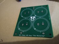
If anyone's wondering what the updated matcher looks like, here it is.
Attachments
I found 10mm fine, but you need to take care with bending the leads as it is on the limit as Johno suggested.Build Guide recommends min 8mm and max 10mm.
Personally, I think 10mm leaves too little lead length on the EF3-4 boards for safe soldering the Vbe TO126 transistors, especially if their leads are bent conservatively a little further from the transistor body.
Hope this helps
- Dan
I have the DER EE LCR Meter DE-5000, I highly recommend this oneDumb question, what is the proper name of the type of meter that can measure low inductor coils like these?
Any suggestions of a decent economical meter to do such measuring?
- Home
- Amplifiers
- Solid State
- DIY Class A/B Amp The "Wolverine" build thread