

Do I need to make then any changes in this front end scheme? Resistor values, match or increase some current mA?if you have them, use them ........ taking care of dissipation
I couldn't find dissipation figure, at least in JFE2140 datasheet
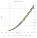
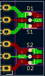
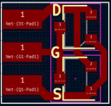
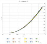
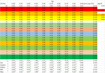
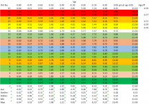
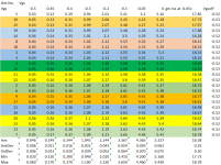
I bought 25 Toshiba 2SK209BL and 2SL209GR, and tested. GR grade is wonderful. Couldn't believe it. They are so good. I designed adaptors for them. Al PCB for double Jfets, and PCB for double JFET deferential pair.
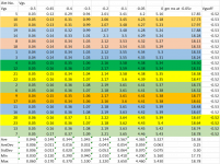
GR gm 18ms at vgs-0.5V, BL 22ms
GR gm 18ms at vgs-0.5V, BL 22ms
Attachments
Last edited:
Do I need to make then any changes in this front end scheme? Resistor values, match or increase some current mA?
of course that you need to set prescribed Iq levels for first and second stage
if you need to know how, prepare all parts, open dedicated thread
I bought 25 Toshiba 2SK209BL and 2SL209GR, and tested. GR grade is wonderful.
GR gm 18ms at vgs-0.5V, BL 22ms
Few people bother to measure at multiple Vgs, so all credit to you.
We bought and traced 100x GR recently, and Idss varies from 3.9 to 4.4mA.
We had batches before as low as 3mA, and as high as 6mA.
So you should consider yourself lucky.
See also :
https://www.diyaudio.com/community/threads/2sk2145-matching-statistics.371427/
This is why I do not recommend 2SK2145, unless you are prepared to throw half away.
(I consider 1% barely acceptable, <0.5% my standard.)
Patrick
I respectfully disagree. It's just not true🙂. Yeah, that sounds logical, but is not necessarily true.It is available, like NP’s BOM implies ‘10P15’, or in two different lead spacings and sizes in the 63VDC model.
Ex:
WIMA MKS 4 4.7uF/ 63VDC/ 40VAC. The are only two options regarding PCM/lead spasing/. PCM15 /MKS4C044704D..../ and PCM22.5 /MKS4C044705B..../. NOT the PCM10 either. Page-53
https://www.mouser.bg/datasheet/2/440/e_WIMA_MKS_4-1139797.pdf
BUT. Mouser provides the following information.
-WIMA MKS4C044704D00KSD
-Mouser #: 505-MKS4C044704DKSSD
-Film Capacitor 4.7uF 63 Volts 10%
-Capacitanse: 4.7uF
-Voltage Rating DC: 63VDC
-Voltage Rating AC: 40VAC
Tolerance: 10%
Lead Spacing: 15mm
----------------------
----------------------
----------------------
Part # Aliases: MKS4-4.7/63/10P15
https://www.mouser.com/ProductDetail/WIMA/MKS4C044704D00KSSD?qs=2G4irm/qADzQpX8Q6Jy%2BYg==
So, what is the meaning of ''10'' /10P15/ after all?
- ''10'' - Tolerance 10%
- ''P15'' - PCM15 /Lead Spasing/ -15mm
Have a look at the 3.3uF 63V options in the data sheet. They are available in 10 and 15mm lead spacing. You are citing the 4.7uF unit - which does indeed have the lead spacing you indicate - but 4.7uF is not the value specified in NP’s BOM. Here’s the datasheet. Lots of alternatives, yes.

Hi, you must add reliable and tweakable. We are demandingAmong the appreciations of DIYers is stuff that works simply, well, and cheap, not necessarily in that order.
 !
!Discussion is occurring which will result in additional holes to keep people happy.
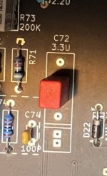
It's impossible to overestimate the ingenuity of builders. Here's an example, where a capacitor PCB footprint can accomodate any lead spacing from 5.0mm to 22.5mm in 2.5mm increments. However, it is now possible to stuff and solder the capacitor incorrectly, resulting in a circuit that doesn't function properly. D'oh !
_
Attachments
If there is going to be a PCB revision I suggest an additional resistor R13 and external connection to optionally allow feedback from the output stage. Basically, the combination of R13 and R4 control both the closed-loop gain and the amount of feedback from the output stage. It has been tested and works well. I will explain this in more detail in a post here or a new thread.
Attachments
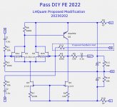
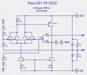
I called it mixed feedback (see below).
This FE is essentially a discrete opamp.
https://www.diyaudio.com/community/...-and-maybe-a-power-whammy.390636/post-7189861
https://www.diyaudio.com/community/...-and-maybe-a-power-whammy.390636/post-7189947
https://www.diyaudio.com/community/...-and-maybe-a-power-whammy.390636/post-7190521
Patrick
Thanks Patrick. I had not noticed your use of mixed feedback before. It is useful for both increasing the damping factor and lowering the output distortion in an easily controlled manner with one resistor. There is also a simple way to use a potentiometer to control the feedback level and keep the closed loop gain "nearly" constant.
Attachments
- Home
- Amplifiers
- Pass Labs
- DIY Front End 2022