@warrjon just wandering how your build is coming along. The last we saw were those beautiful CNC parts.
S.
I've been away sailing so nothing has happened in my world. I'm going to see Kev on Saturday he has a few wheels made for me to test. We are getting there slowly. The bridge is drawn up in CAD and the rail carriers are made.
Truepoint has closed it's website so we had the axles ground and polished locally. The finish on them is mirror but they did cost $85 each x 4 so not cheap.
Thanks for the link Mike, I’ll see if there is any info on that thread about phenolic paper boards. A lot more affordable, £25 per sheet at my local electrical shop. I even think toolstation stock it (UK). I agree, there must be an affordable DIY approach to plinth building. After all Permali and the like, were not conceived to be damping panels it’s just lucky for the audio community that they do possess intrinsic damping properties.
S.
My SP10 plinth is Permalli (similar to Panzerholtz) it has fantastic damping properties. I tested the SP10 motor in the previous resin/bentonite plinth and then when I swapped it to the Permalli. The Permalli had 20dB less energy above 200Hz in an impulse test.

Here are a few pics of the new TT and LTA mocked up to see what it'll look like.
Pic 2 is the new wheels, Tyre is hardened tool steel fitted to an aluminium hub. The last pic are the tyres before and after having the centers wire cut. Next operation is to part off the ends of the axles and jig bore for the carbide pivot pins.


Pic 2 is the new wheels, Tyre is hardened tool steel fitted to an aluminium hub. The last pic are the tyres before and after having the centers wire cut. Next operation is to part off the ends of the axles and jig bore for the carbide pivot pins.
You always need to remember that all this tool, hardened steel needs to be rolled along rails by the thinnest tip of a diamond needle in a pliable vinyl material.
No matter how smoothly the wheels and rails are polished, it will be very difficult for the diamond tip of the needle to set this “railroad” in motion, especially if there is eccentricity of the vinyl record, and eccentricity is almost always present to a greater or lesser extent.
No matter how smoothly the wheels and rails are polished, it will be very difficult for the diamond tip of the needle to set this “railroad” in motion, especially if there is eccentricity of the vinyl record, and eccentricity is almost always present to a greater or lesser extent.
One would think lowest moving mass and friction are pre requisites, that said Clearaudio have managed it for decades. I look forward to more engineering porn.
Hi Havun,
The problem of high bearing friction is not anywhere near the problem that you suggest it to be, even on severely eccentric records.
Whilst developing the type of wheels and bearings being built by Warren (Warrjon) I built a test rig for measuring friction. I used a combination of mathematical modelling and these measurements to determine the expected deflection of the cantilever due to eccentricity. These models included not just bearing friction but also the inertial effect of the higher carriage mass.
Eccentricity not only moves the record from side to side it also moves it forwards and backwards. The forward and backwards movement is actually the more problematic as it causes the speed of the record past the stylus to vary (wow) and causes a lateral tracking error. For a 0.5mm eccentricity, which would result in a 1mm back and forth movement, will result in a maximum tracking error of ~0.2° at the start of the record and ~0.46° at the end. 0.5mm is a pretty severe eccentricity, way above DIN specs.
On the same record with a 0.5mm eccentricity , my arm which is very similar to Warren's, would result in a maximum cantilever deflection of around 0.4°. This may, at first glance, look like a large deflection. I also calculated the deflection for typical pivoted arms and they came just below this figure 0.25-0.3°. This is assuming that anti-skating is set as close to perfectly as possible.
Now you have to remember that this is on a severely eccentric record. On a perfectly centered record the error due to inertia goes away leaving only bearing friction which would result in a deflection of ~0.2°.
These deflections were calculated based on my old cartridge, an Ortofon 2M Black which has a high compliance of 22μm/mN. My current cartridge has a compliance of 16μm/mN. This will result in the calculated deflections being reduced by almost a quarter.
Meanwhile a 12" pivoted arm would have an average tracking error of over 1°. It would be even higher with a 9" arm. Regardlessof ccompliance.
It must also be pointed out that, due to the higher lateral effective mass, the amount that the cartridge body moves will be, especially in the bass, much lower than with a conventional pivoted arm.
I did take a video of my old cartridge tracking a record where I had filed out the centre hole to give an eccentricity of 1.6mm. This resulted in the carriage moving back and forth by 3.2mm (1/8").
Hopefully this link works.
As you can see virtually no cantilever definition is visible.
The video corroborates my calculations. It's not an issue.
Hello, I didn’t find the video very informative, it feels like you’re just moving the camera left and right, because in the frame not only the Ortofon head moves, but also everything behind it😛.
I should add, when I was developing my arm I did originally use ball-race bearings, similar to those used by Clearaudio. Even using very high quality ceramic hybrid bearings resulted in friction that was 4 times as high as my current design. The Ball-race bearings also varied a lot as they rotated depending on how the balls were positioned. My jeweled pin bearings are much more consistent.
The main problem with the ball-race bearings is chatter due to the unloaded balls being loose and able to move around.
Another advantage of the pin bearing design is they couple the carriage to the rail more effectively. The carriage is basically mounted on spikes.
You will find that the majority of the most highly rated arms use spikes for their main bearing elements.
Kuzma, SAT, Graham etc.
Niffy
I can assure you that the camera was being held completely still.Hello, I didn’t find the video very informative, it feels like you’re just moving the camera left and right, because in the frame not only the Ortofon head moves, but also everything behind it😛.
The frame is zoomed in so that the end of the cantilever is clearly visible. Unfortunately this does mean that the carriage, which of course moves with the cartridge, fills most of the rest of the frame. If I zoomed out enough to include a stationary reference you would no longer be able to see the cantilever, which would defeat the purpose of the video.
As a bonus the video also shows how well my clamping system works, there is barely any vertical movement.
Niffy
I tried a similar tonearm with rollers and ball bearings, it was disappointingly bad, but if you used sleeve bearings with gemstones like ruby, then I would like to see your design, very interesting!
My design has come a long way from ball bearings.
It runs on tungsten carbide rails. The wheels have tungsten carbide rims on titanium and aluminum hubs. The bearings are sapphire vees with tungsten carbide pivots.
The key to performance is hardness of the materials. Sapphire and tungsten carbide are two of the hardest engineering materials available.
Unfortunately diamond isn't available in the sizes required for this project.
Niffy
Yes it started life as an SP10mk2. The only SP10 bits that remain are the motor stator, magnet and electronics. A completely new motor housing has been machined to increase rigidity and incorporate an inverted bearing. The electronics will be moved from the SP10 chassis to a custom made enclosure.Just to get this straight.
That is an SP10 right?

One would think lowest moving mass and friction are pre requisites, that said Clearaudio have managed it for decades. I look forward to more engineering porn.
Friction and sticktion yes but not mass so long as the mass is not so great that inertia become a problem. It is actually inertia usually called Effective Mass (EM) in audio that holds the cartridge body still. If the system had ZERO EM then the cartridge would have no output.
@niffy 's design does a couple of things. It has a very stiff carriage moving what would be arm wand resonance out of the audio band, WOW is this audible. Next is high lateral EM holding the cartridge still allowing the stylus to track bass modulation better, this arm digs deep. with well damped lower vertical EM preventing the carriage bouncing the cartridge.
The driving force that moves the carriage back and forth is created by the positive castor of the stylus being forward of the pivot (cart suspension) this works like a shopping trolley wheel so the carriage follows the diamond.
I know nothing about the math involved, but I'm sure it's not a trivial set of physical compromises, good luck with it. Well out of my wheel house and as such I'm in awe of the engineering required.
Horizontal stylus deflection can be derived directly from the cartridge signal. If you use a flat response preamp and capture the signal with a DC coupled or very extended bass response (2 Hz) computer sound card line level input or USB interface the signal can be integrated to produce a displacement value. The cartridge output voltage is proportional to stylus velocity. I did this with my Technics SL-5Q linear tracking table and found that I had misadjusted the feedback on the servo drive of the tonearm carriage. Playing a test record with a 1 kHz 5 cm/s track allows for calibrating the displacement.
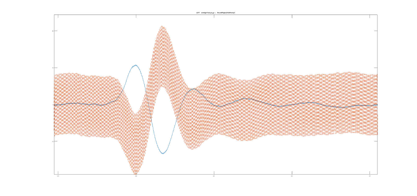
1 kHz 5 cm/s tone in R channel no signal in the L channel from Ortofon test record. R channel is dashed line, producing the wide pattern. The horizontal graph ticks are 0.1 seconds. The vertical axis ticks are at 10 um. Displacement calculated by integrating the cartridge output and scaling to um. The large slow waveform is about 12 Hz and low damping, corresponding to the tonearm-stylus resonance for side to side motion of the cartridge.
So this waveform was due to the carriage drive pulsing the motion of the arm about every 1.5 seconds rather than moving it smoothly. After making adjustments this was reduced. The curves go in opposite directions as the left and right channels measure horizontal motion in opposite polarity.
It would be great to see this kind of measurement for the DIY arms. Until I started making and documenting measurements I could only guess at the performance of my tonearm. I think it would be fun to design a linear tracking arm. I would like to make it as simple as possible and leverage 3D printing for many of the parts. I will have to work through the few hundred pages of this thread.
Last edited:
Interesting Olsond, but beyond my mathematical comprehension at the moment. I understand the principle of integration in relation to a curve or function but not how it can give these absolute conclusions, so am interested to know more.
I guess there are various assumptions made about the relationship of the output signal to the lateral displacement of the stylus when considering down towards a DC level.
In the case where you have a known and consistent pulsing input rate to the driven carriage i can see how values could be viewed and after modifications compared, but i am puzzled with so many aspects involved how this could be used to isolate the absolute value of the signal and attribute it to the single cause of side deflection alone.
I became interested in measurements through suggestions of folk on this thread and have made hundreds if not thousands of comparisons of different measurements from frictions to signals. From that i learnt a little about the causes of various aspects of the measurements, and somethings about the experimental errors involved, but could never isolate anything specific like this.
Looking forward to learning more if you have the patience!
M
Hi Mike, I'll try my best to explain. I started digging into this three months ago for several hours a day, so it isn't obvious.
Inertial navigation systems are used on spacecraft, aircraft, and your phone to track position for navigation. These systems use an accelerometer to measure acceleration at a high sample rate. The acceleration values are then integrated twice to produce velocity and then position values.
A simple integrator for a stream of data samples is implemented by multiplying each sample by the sample interval time and then adding that to a sum. This summed value will grow or shrink with positive or negative sample values, such that the sum will be equal to the area under the curve or the integral of the input signal samples. If you measured the frequency response of an integrator it is a sloped line that drops 6 dB per octave with rising frequency such that it has infinite gain at DC and zero gain at infinite frequency.
The typical phono cartridge produces a voltage by moving a magnet in relation a coil. The voltage induced in the coil is proportional to the velocity of the stylus that is moving either the coil or the magnet in the cartridge through a lever. The coil and magnet system for the left channel are wired to produce a positive voltage proportional to the motion of the stylus at 45 degrees moving upwards and towards the outside of the record. So an upward slope on the inside groove wall will produce a positive L channel signal. The right channel coil is wired to produces a positive voltage for motion of the stylus downward and to the outside of the record. So a downward slope, or falling into a depression in the outside groove wall, produces a positive voltage on the R channel.
So to calculate the stylus displacement, the voltage from each channel, proportional to velocity, can be integrated (summed) over time to produce displacement values.
To orient the displacement values to be positive for upward motion of the stylus from both channels, the signal from the R channel needs to have the polarity reversed as it's velocity is measured with positive polarity for downward motion.
To isolate the horizontal motion of the stylus the L + R channels are summed. The horizontal values add and the vertical contributions being of opposite signs cancels.
To isolate the vertical motion of the stylus the L - R signal is formed. This subtraction cancels the horizontal motion from the two signals and sums the vertical signals. Both of these are a 45 degree coordinate transformation.
To produce the plot I show in my earlier post, inverted the sign of the R channel signal and integrated each signal individually to produce left and right position traces. So a positive value on the graph represents a positive vertical displacement on the record surface, up and to the outside for the L channel and up and to the inside for the R channel to be specific. So for vertical displacement both signals would rise together. For horizontal displacement the signals are identical but in opposite directions on this graph. I was playing the Ortofon test record track with a 1 kHz 5 cm/s tone on the R channel only. So the rapid up and down motion is the signal. The Left channel had no signal on the record, so all the deflection is from rumble or external disturbance of the tone arm. As both channels show a large slow displacement in the opposite direction, this is a horizontal displacement of the stylus. The low frequency matches the expected tone arm resonance.
If the record had mono bass notes recorded on it, they would also appear as low frequency horizontal deflections in the graph. Hopefully I didn't make any mistakes in my description.
Last edited:
- Home
- Source & Line
- Analogue Source
- DIY linear tonearm